Stove burner

A technology of burners and burner caps, applied in the direction of burners, gas fuel burners, combustion methods, etc.

Inactive Publication Date: 2015-02-04
RINNAI CORP
View PDF7 Cites 0 Cited by
  • Summary
  • Abstract
  • Description
  • Claims
  • Application Information

AI Technical Summary

Problems solved by technology

[0004] However, depending on the user, even if the burner cap floats from the burner head, the ignition operation may be performed without noticing that it is a mis-assembled state.
In this case, since the flame hole is not normally formed between the burner head and the burner cap, problems such as backfiring and poor combustion may occur.

Method used


Image

  • Stove burner
  • Stove burner
  • Stove burner

Examples


Embodiment Construction

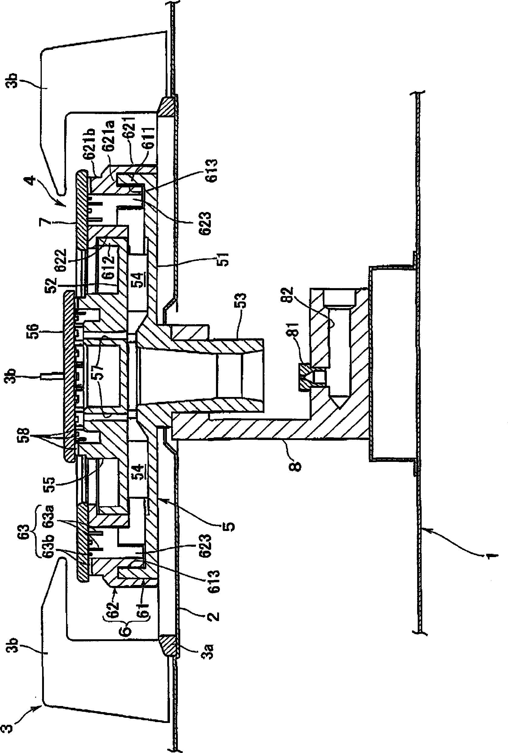
[0017] refer to figure 1 , 1 denotes the main body of the stove, and 2 denotes a panel covering the upper surface of the main body 1 of the stove. The fire support 3 is placed on the panel 2, and the burner 4 for stoves 4 which concerns on embodiment of this invention is installed in the part surrounded by the fire support 3. In addition, the fire stay 3 is formed by attaching a plurality of (for example, four) fire stay claws 3b to an annular fire stay frame 3a seated on the panel 2 so that there are intervals in the circumferential direction. .

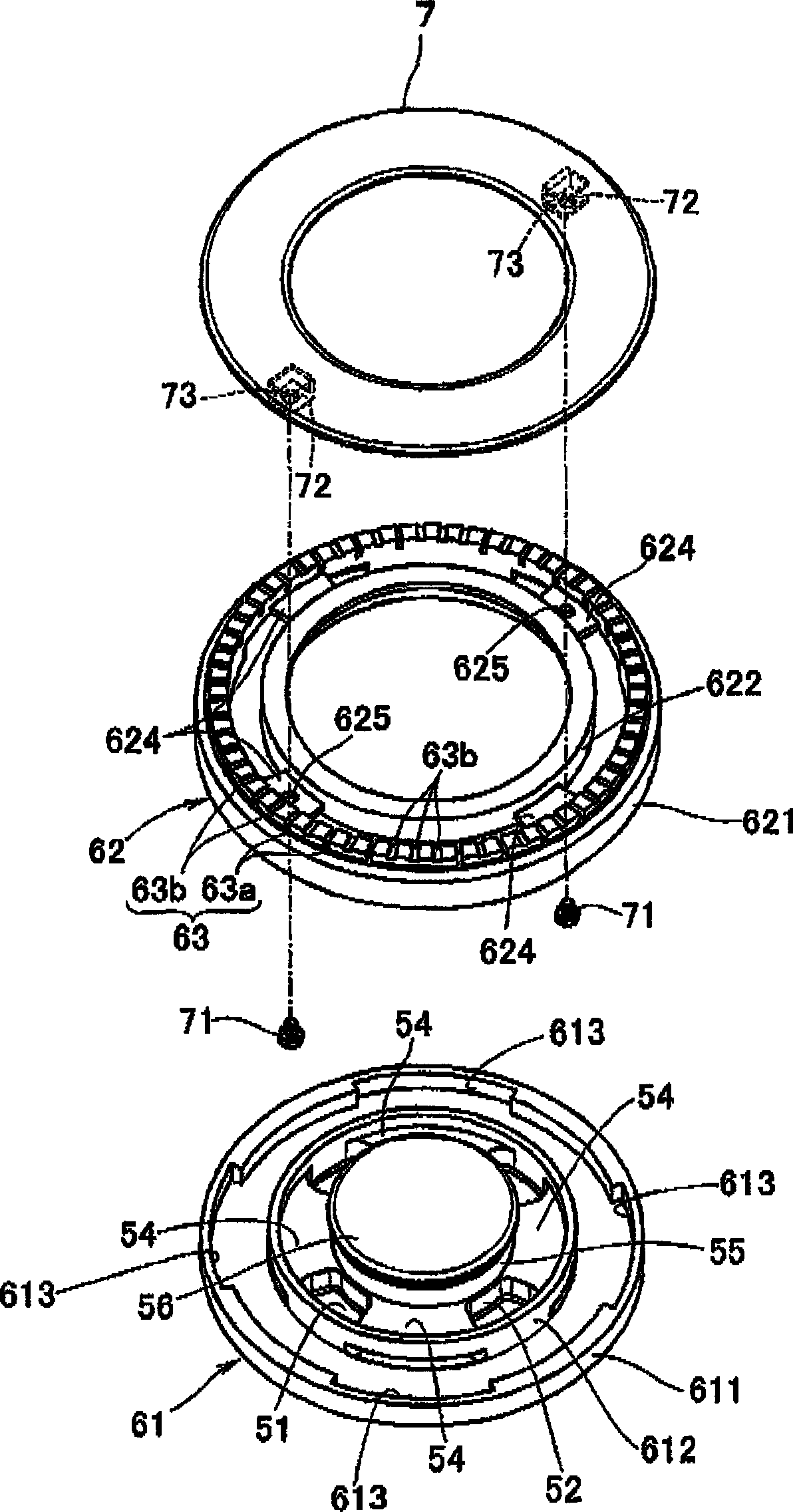
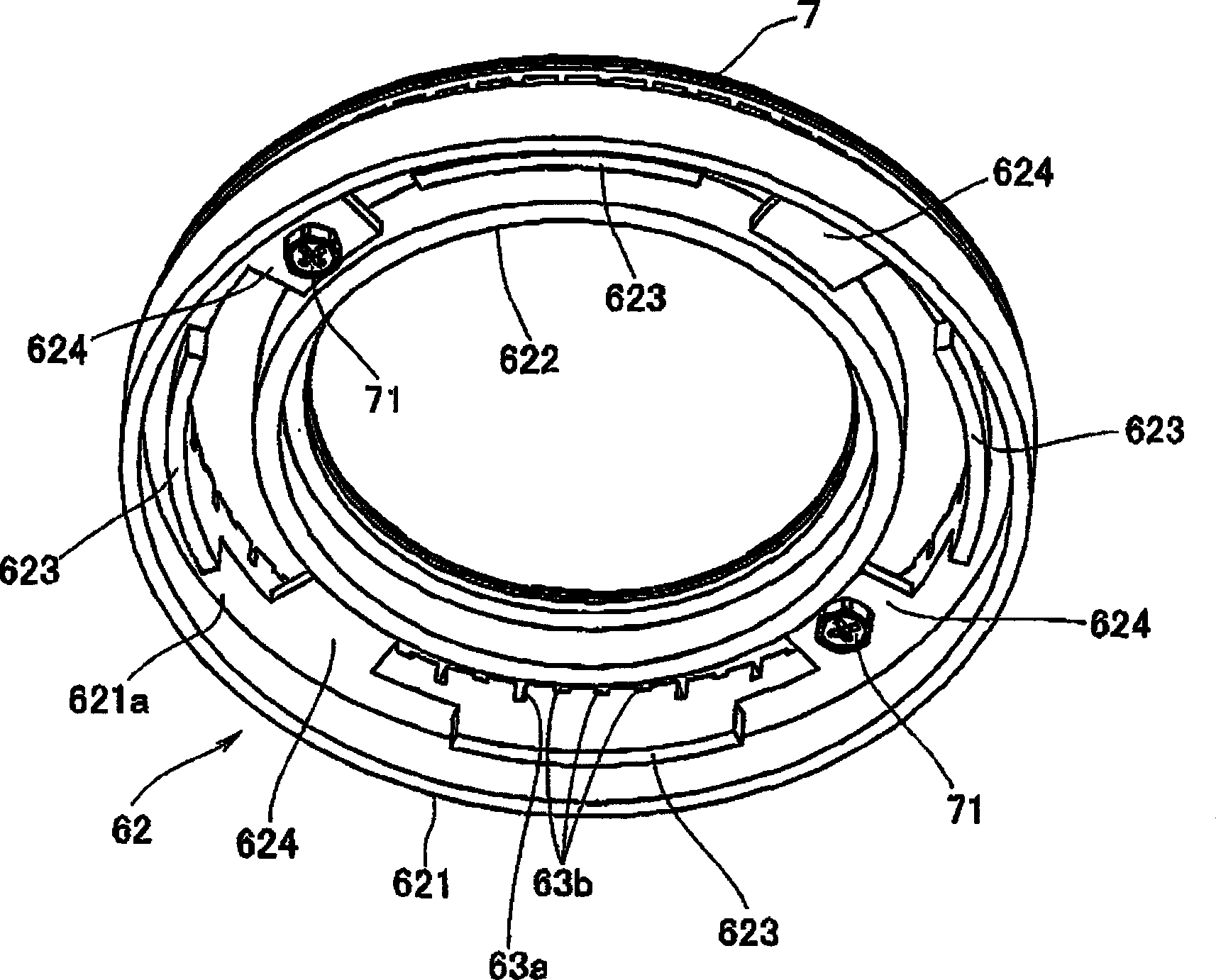
[0018] The burner 4 for a stove includes a burner body 5 having a ring-shaped burner head 6 opening upward, and a burner cap 7 provided on the burner head 6 . In addition, the burner head 6 is divided into two parts, a lower burner head 61 and an upper burner head 62 .

[0019] The burner body 5 has a lower plate portion 51 supported by a support block 8 provided in the furnace body 1 , and an upper plate portion 52 having a smal...


PUM


Abstract

The invention provides a stove burner, which comprises a burner main body (5) with a burner head (6) and a burner cap (7). The stove burner can prevent bad combustion such as backfire, etc. when the stove burner is assembled in a faulty way. The burner head (6) is divided into a lower burner head (61) and an upper burner head (62). The burner cap is fixed or integrally formed on the upper burner head. A concave part (613) is radially formed on a part of the circumference of the outer peripheral wall (611) of the lower burner head (61). The upper burner head (62) is provided with a positioning piece (623) to be inserted in the concave part (613) in a drooping way. When a faulty assembling case in which the positioning piece (623) abuts against the outer peripheral wall upper end of the lower burner head (61) occurs, the lower ends of the outer pheripheral wall (621) and the inner peripheral wall (622) of the upper burner head (62) are embedded in the outer peripheral wall (611) and the inner peripheral wall (612) of the lower burner head (61).

Description

technical field [0001] The present invention relates to a stove burner comprising a burner body and an annular burner cap, wherein the burner body has an annular burner head opening upward, and the burner cap is provided on the burner head. and a flame hole is formed between the burner cap and the burner head, and the flame hole is used to spray the mixed gas supplied into the burner head. Background technique [0002] Conventionally, in such a burner for a stove, the burner cap is detachably mounted on the burner head. In this case, it is necessary to prevent the problem that the once-removed burner cap is placed on the burner head in an incorrectly assembled state deviated from the correct position. The reason for this is as follows, for example. That is, in the case where the flame holes corresponding to the claws of the flame holder (fire holder claws) placed on the panel of the stove are provided as small flame holes, it is necessary to install the burner cap at the c...

Claims


Application Information

Patent Timeline
Patent Type & Authority Patents(China)
IPC IPC(8): F23D14/02F23D14/46
Inventor 佐藤裕康
Owner RINNAI CORP
Why Eureka
Try Eureka