
Pressure control valve

A pressure-regulating, adjustable technology, applied in the field of pressure-regulating valves, which can solve problems such as high manufacturing and installation costs

Inactive Publication Date: 2014-09-03
PIERBURG GMBH & CO KG NEUSS
View PDF4 Cites 0 Cited by
  • Summary
  • Abstract
  • Description
  • Claims
  • Application Information

AI Technical Summary

Problems solved by technology

In order to guarantee the sealing closure, strict requirements are placed on the manufacturing precision of the electromagnetic drive and the pressure control valve, which in turn leads to high manufacturing and installation costs

Method used


Image

  • Pressure control valve

Examples


Embodiment Construction

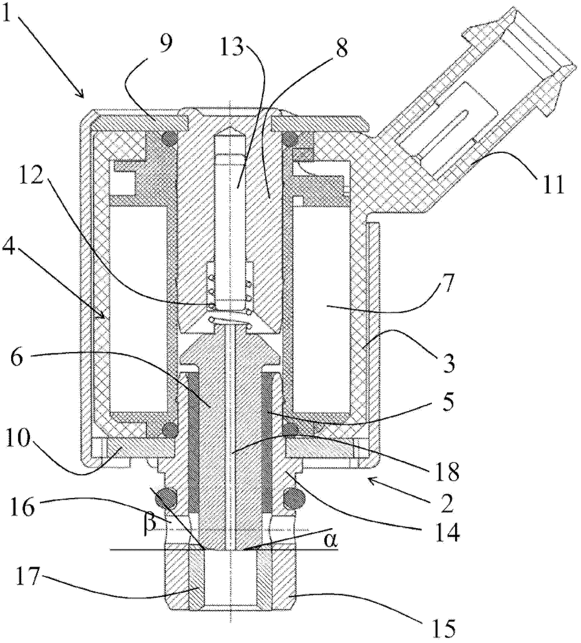
[0012] The control valve 1 according to the invention has a housing 2 which is basically designed as a two-part housing. The upper part 3 has an electromagnetic drive unit 4 which acts on an armature 6 arranged axially displaceable in a bearing 5 . Electromagnetic drive 4 essentially comprises a coil 7 , a core 8 and a flux guide comprising a return plate 9 and a yoke 10 . The plastic housing also has a plug 11 for controlling the pressure regulating valve. The core 8 is in this case sandwiched within the upper part 3 .

[0013] The electromagnetic drive 4 acts on an armature 6 which in this case serves as the valve stem and valve closure member of the on / off valve. The armature 6 is here pretensioned in the closed position by the spring 12 relative to the core 8 . The spring 12 is guided by a pin 13 which, in the installed state, is arranged adjustably within the core and at the same time serves as an upper stop element for the armature 6 . The armature 6 is in turn mount...


PUM


Abstract

The invention relates to a pressure regulating valve with a housing having a coil wound on a bobbin, an armature axially displaceable in a bearing, a core and a flux guide, and the pressure regulating valve The regulating valve has a connecting hole and a connecting head, wherein the connecting head has a valve seat for the armature, wherein the housing is basically designed in two parts, wherein the lower part has the connecting head and connecting hole and is arranged in a frictional or form-fitting manner In the upper part of the housing, wherein a bearing bush for the armature is provided in the part of the connection head directed towards the core, and a stop bush for the armature is provided in the opposite part of the connection head.

Description

technical field [0001] The invention relates to a pressure regulating valve with a housing having a coil wound on a bobbin, an armature axially displaceable in a bearing, a core and a flux guide, and the pressure regulating valve The control valve has a connection bore and a connection head, wherein the connection head has a valve seat for the armature. Background technique [0002] Such pressure regulating valves are used in particular in hydraulic regulating devices, in the control of automatic transmissions of motor vehicles, or also in combination with pressure- or flow-controlled engine oil pumps. In this case, the pressure regulating valve can be a so-called on / off valve or also a so-called modulating valve which can adjust the flow in a stepless manner. For example, mention is made here of the on / off valve known from DE 197 16 185 A1. Here, an electromagnetically driven armature cooperates with the valve seat to fluidly connect the connection opening with the outflo...

Claims


Application Information

Patent Timeline
Patent Type & Authority Patents(China)
IPC IPC(8): F16K1/36F16K1/42F16K31/06
CPCF16K31/0693F16K1/36F16K1/42F16K31/0658F16K27/029F16K1/38
Inventor 沃纳.布斯弗兰兹-约瑟夫.施内尔克罗尔夫.多尔曼
Owner PIERBURG GMBH & CO KG NEUSS
Learn More