
Small centrifugal fan

A centrifugal fan, a small technology, applied in the direction of mechanical equipment, machine/engine, liquid fuel engine, etc., can solve the problems of high noise, small air volume, low efficiency, etc., and achieve the effect of reducing noise, increasing flow, and increasing air volume

Inactive Publication Date: 2013-01-16
张家港安锐格机电设备有限公司
View PDF7 Cites 0 Cited by
  • Summary
  • Abstract
  • Description
  • Claims
  • Application Information

AI Technical Summary

Problems solved by technology

[0002]At present, most of the domestic industries that need fans use axial flow fans, but axial flow fans have the following disadvantages: complex structure, many faults, difficult maintenance, low efficiency, Large noise, low static pressure, small air volume, poor stability when working in parallel

Method used


Image

  • Small centrifugal fan
  • Small centrifugal fan
  • Small centrifugal fan

Examples


Embodiment Construction

[0015] The preferred specific embodiments of the present invention will be described below in conjunction with the accompanying drawings.

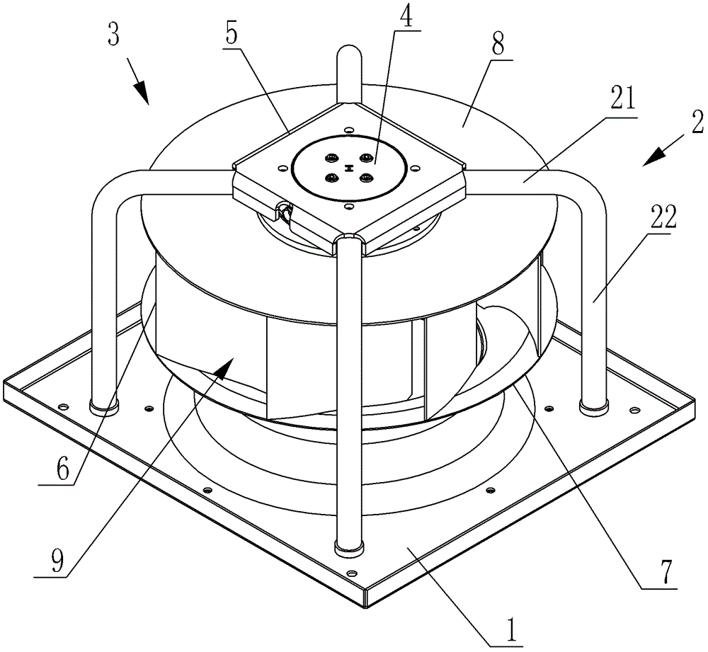
[0016] Such as image 3 As shown, the small centrifugal fan includes a motor 4, an impeller 3 fixedly connected to the rotating shaft of the motor 4, a support plate 5 connected in rotation with the end of the rotating shaft of the motor 4, parallel to the chassis 8 and connected to the The base plate 1 fixedly connected with the air ring, and a plurality of connecting rods 2 connected between the support plate 5 and the base plate 1 .

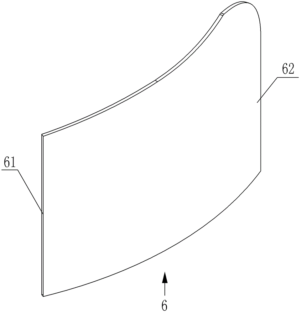
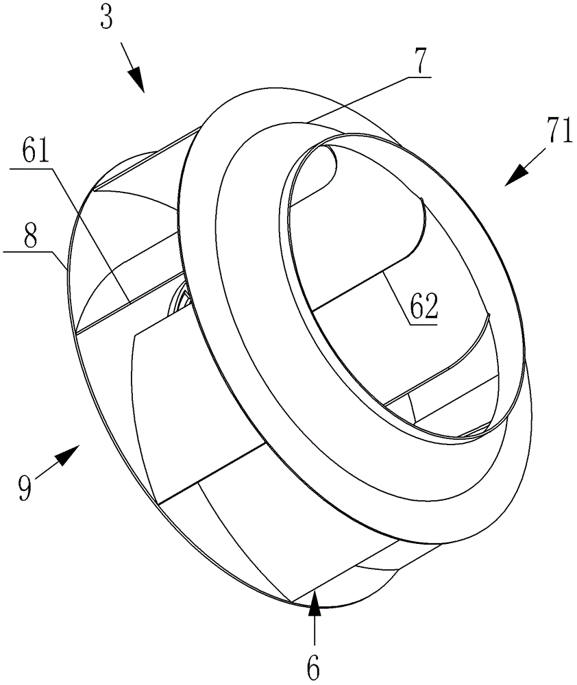
[0017] Such as figure 2 As shown, the impeller 3 includes a chassis 8 , an air inlet ring 7 arranged coaxially with the chassis 8 , and a plurality of blades 6 fixed between the chassis 8 and the air inlet ring 7 .

[0018] The inner ring of the air inlet ring 7 is an air inlet 71 where the airflow flows in, and each hole surrounded by the chassis 8, the air inlet ring 7 and two adjacent blades ...


PUM


Abstract

The invention relates to a small centrifugal fan, which comprises a motor and an impeller fixedly connected with the rotating shaft of the motor. The impeller includes a chassis, an air inlet ring coaxially arranged with the chassis, and a Multiple blades, the inner ring of the air inlet ring is the air inlet for the airflow to flow in, the holes surrounded by the chassis, the air inlet ring and the two adjacent blades are the air outlets, and the centrifugal fan also includes A support plate that is rotatably connected to the end of the rotating shaft of the motor, a base plate that is parallel to the chassis and fixedly connected with the air inlet ring, and a plurality of connecting rods connected between the support plate and the base plate. The present invention uses slender connecting rods, bottom plates and support plates to fix the motor and impeller, and the connecting rods fixed near the air outlet are slender and will not block the outflow of air from the air outlet, thereby increasing the flow rate of the air and improving the The air volume is also reduced, and the noise generated by the airflow impacting the connecting rod is also reduced.

Description

technical field [0001] The invention relates to a small centrifugal fan. Background technique [0002] At present, most domestic industries that need fans use axial flow fans, but axial flow fans have the following disadvantages: complex structure, many faults, difficult maintenance, low efficiency, high noise, low static pressure, small air volume, and stability when working in parallel poor. Contents of the invention [0003] The object of the present invention is to provide a small centrifugal fan. [0004] In order to achieve the above object, the technical solution adopted by the present invention is: a small centrifugal fan, which includes a motor, an impeller fixedly connected with the motor shaft, and the impeller includes a chassis, and an air inlet ring coaxially arranged with the chassis And a plurality of blades fixed between the chassis and the air inlet ring, the inner ring of the air inlet ring is the air inlet for the airflow to flow in, and each hole sur...

Claims


Application Information

Patent Timeline
Patent Type & Authority Patents(China)
IPC IPC(8): F04D25/08F04D29/28F04D29/30
Inventor 钱建刚
Owner 张家港安锐格机电设备有限公司
Learn More