
Daylighting device for guiding light by using rotary reflecting mirror

A technology of reflectors and rotating shafts, applied in reflectors, lighting devices, using sunlight, etc., can solve problems such as depression, dark and humid indoor environments, and increase indoor illuminance

Active Publication Date: 2011-11-23
SHANGHAI JIUNENG ENERGY SCI & TECH DEV
View PDF5 Cites 3 Cited by
  • Summary
  • Abstract
  • Description
  • Claims
  • Application Information

AI Technical Summary

Problems solved by technology

[0002] At present, many buildings at home and abroad are affected by the orientation or surrounding environment, especially in China, a large number of old houses in the crowded alleys left over from the past have unsatisfactory natural lighting conditions all the year round. The distance between them is very small, and the indoor environment of these houses is dark and humid all the year round, regardless of the short sunshine time or no light. On the one hand, it is easy to form a breeding environment for germs, which is not conducive to people's physical and mental health. concept to improve the quality of life of the residents living here
Then, due to the lack of natural light in the case of short sunshine time or no light, the mood is greatly depressed, and only electric light source lighting can be used to increase the indoor illuminance, which increases the cost of lighting and causes waste of energy.

Method used


Image

  • Daylighting device for guiding light by using rotary reflecting mirror
  • Daylighting device for guiding light by using rotary reflecting mirror

Examples


Embodiment Construction

[0006] The present invention will be further described below in conjunction with accompanying drawing:

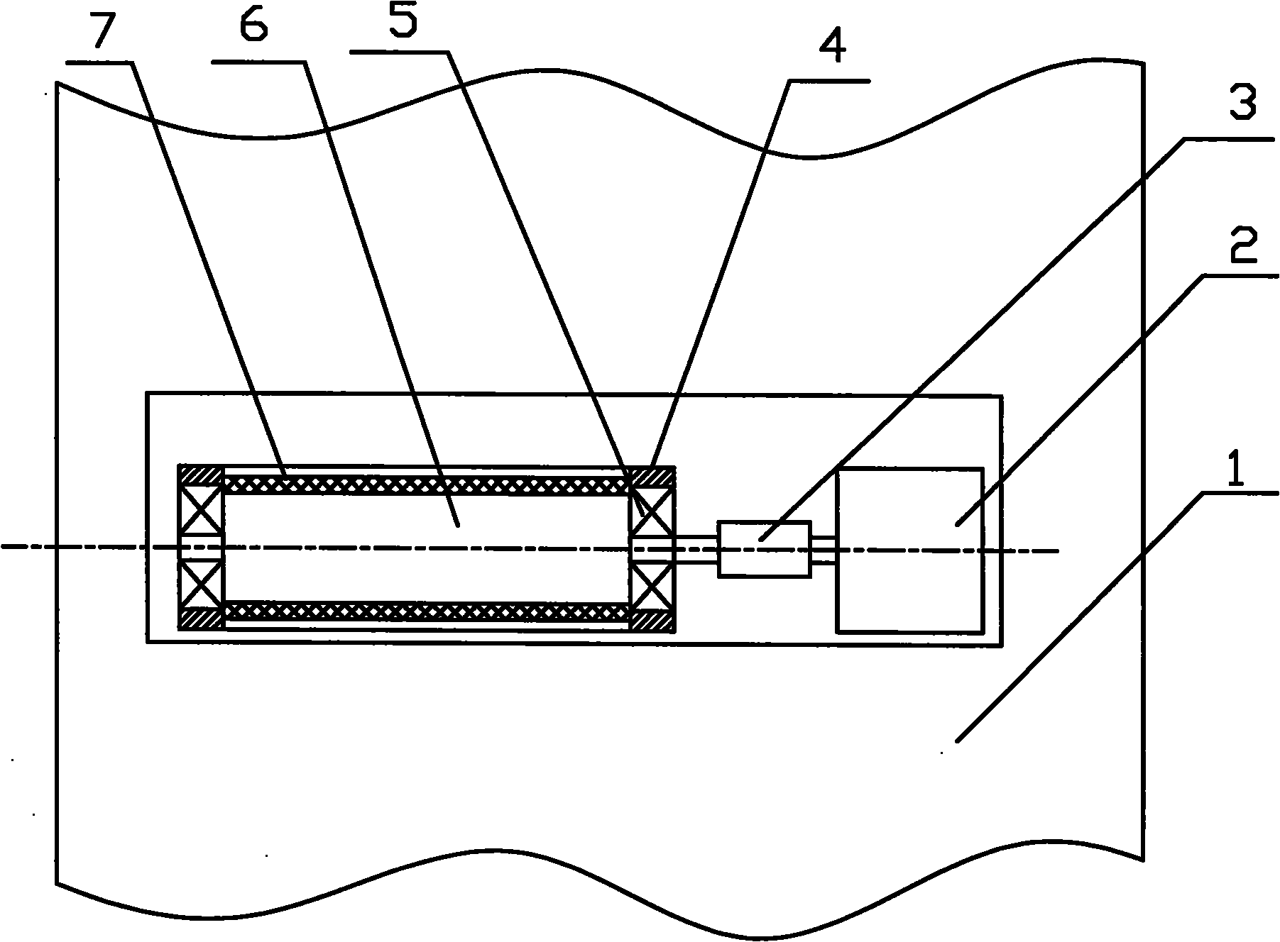
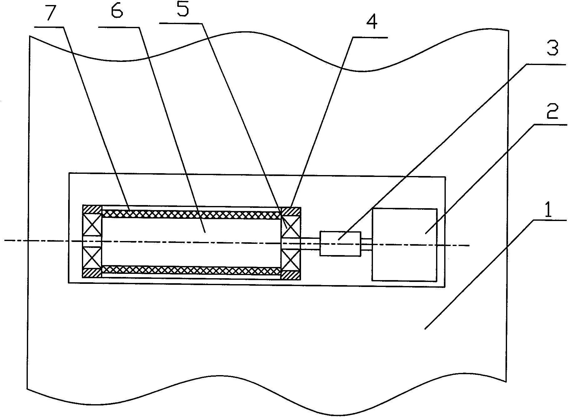
[0007] See attached figure 1 , the whole device is located on the bracket set in the hole opened by the outer wall 1, and the second bearing seat 4 is fixed on the bracket, and the bearing seat 4 is provided with a bearing 5, and a rotating shaft 6 is flexibly fixed between the two bearings 5, and the rotating shaft 6 One end protrudes from the bearing 5 and is fixed with the coupling 3. The rotating shaft 6 is connected to the motor 2 fixed on the bracket through the rotating shaft 6. The circumferential surface of the rotating shaft 6 is axially fixed and covered with convex reflections on the surface of the outer light-receiving surface. The mirror surface 7 is made to have a polygonal structure, and the convex shape of the light-receiving surface is a triangle.

[0008] See attached figure 1 , the whole device is located on the bracket set in the hole opened by the ou...


PUM


Abstract

The invention discloses a daylighting device for guiding light by using a rotary reflecting mirror. The whole device is arranged on a bracket in a hole which is formed in a building; two bearing seats are fixed on the bracket; bearings are arranged in the bearing seats; a rotary shaft is adjustably fixed between the two bearings; one end of the rotary shaft extends out of the bearings and is fixed with a coupling; the rotary shaft is connected with a motor which is fixed on the bracket by the coupling; and reflecting mirror surfaces of which surfaces of outer light-receiving planes are convexare axially fixed and distributed on the circumferential surface of the rotary shaft. The daylighting device for guiding the light by using the rotary reflecting mirror has the advantages that: the obvious defect that illumination is performed only by using an electric light source under the condition of short sunshine duration or no illumination is overcome; the reflecting mirror surfaces on thecircumferential surface of the rotary shaft guides and refracts natural light into a room, so a house lack of the natural light can be irradiated by the natural light; indoor intensity of illumination is improved; daylighting cost is reduced; energy sources are saved; and the daylighting device is favorable for the physical and psychological health of people.

Description

technical field [0001] The invention relates to a light-guiding device using a rotating reflector, which relates to the technical field of design and manufacture of natural light lighting equipment, and is applied to a light-gathering device for collecting sunlight and refracting light. Background technique [0002] At present, many buildings at home and abroad are affected by the orientation or surrounding environment, especially in China, a large number of old houses in the crowded alleys left over from the past have unsatisfactory natural lighting conditions all the year round. The distance between them is very small, and the indoor environment of these houses is dark and humid all the year round, regardless of the short sunshine time or no light. On the one hand, it is easy to form a breeding environment for germs, which is not conducive to people's physical and mental health. concept to improve the quality of life of the residents living here. Then, due to the lack of ...

Claims


Application Information

Patent Timeline
IPC IPC(8): F21S11/00F21V7/04F21V14/04
Inventor 李钊明林东
Owner SHANGHAI JIUNENG ENERGY SCI & TECH DEV
Learn More