

Air guiding device for air-conditioner indoor machine
A technology of air conditioner indoor unit and air guide device, which is applied in the direction of air flow control components, etc., which can solve the problems that the size of the air guide plate cannot be made too large, the continuity of the appearance of the air conditioner is not good, and the air supply distance is not far enough, etc. Achieve ideal air guiding effect, simple structure, and improve aesthetics
- Summary
- Abstract
- Description
- Claims
- Application Information
AI Technical Summary
Problems solved by technology
Method used
Image

Examples
Embodiment Construction
[0033] The present invention will be further described below in conjunction with the accompanying drawings and embodiments.
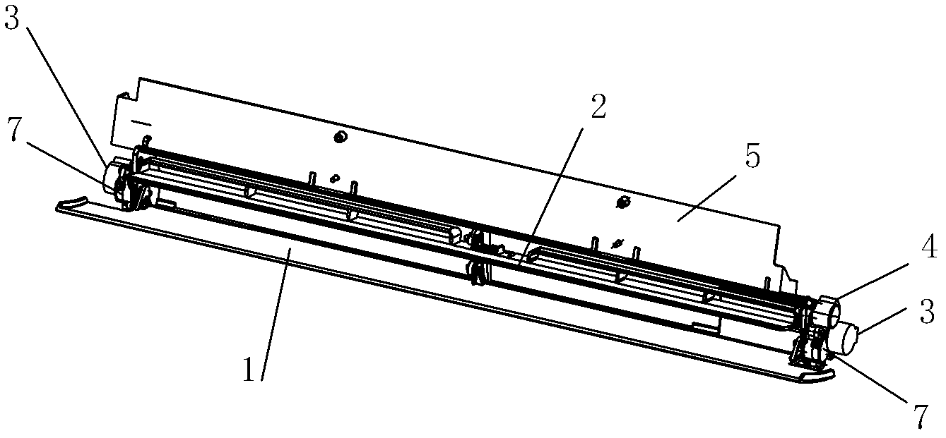
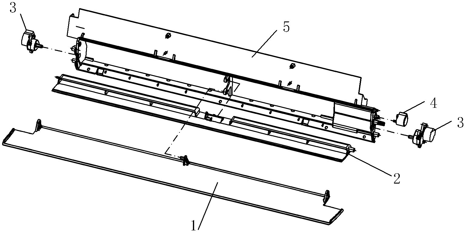
[0034] see Figure 1-Figure 16 , The air guiding device of the indoor unit of the air conditioner includes an air outlet frame 5 arranged on the indoor unit, an air outlet is arranged in the air outlet frame 5, and an air guide plate is arranged at the air outlet.
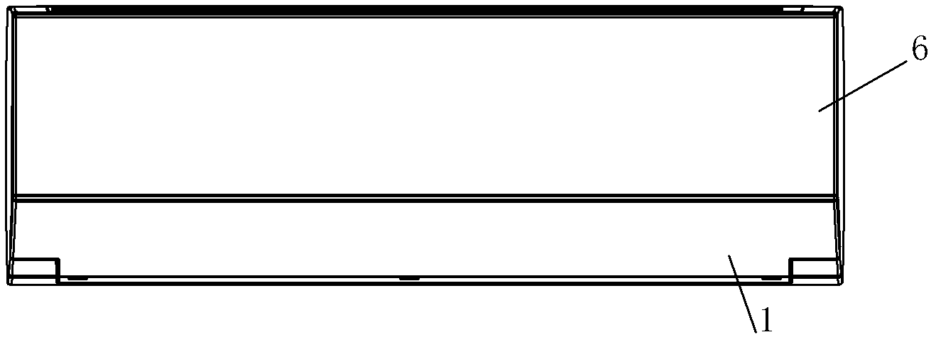
[0035] The wind deflector includes an outer wind deflector 1, and the width of the outer wind deflector 1 is greater than or equal to the width of the air guide opening. The outer wind deflector 1 is a T-shaped structure with a wide top and a narrow bottom. The width of the upper end of the outer wind deflector 1=the width of the panel 6 on the indoor unit. The air outlet frame 5 is provided with a motor assembly 3 , and the output shaft of the motor assembly 3 is in contact with the shaft hole of the outer wind deflector 1 . The outer wind deflector 1 is arranged at the lower part of the...
PUM
 Abstract
Description
Claims
Application Information