
Channel initialization method for distributed cognitive radio network

A technology of cognitive radio and initialization method, which is applied in the field of channel initialization of distributed cognitive radio network, and achieves the effect of solving the difficulty of initial networking

Inactive Publication Date: 2011-11-23
UNIV OF ELECTRONICS SCI & TECH OF CHINA
View PDF2 Cites 8 Cited by
  • Summary
  • Abstract
  • Description
  • Claims
  • Application Information

AI Technical Summary

Problems solved by technology

[0004] The purpose of the present invention is to solve the problem of normal communication between nodes and late network nodes being able to correctly access the network when the network is initially established, and proposes a channel initialization method for a distributed cognitive radio network

Method used


Image

  • Channel initialization method for distributed cognitive radio network
  • Channel initialization method for distributed cognitive radio network
  • Channel initialization method for distributed cognitive radio network

Examples


Embodiment 1

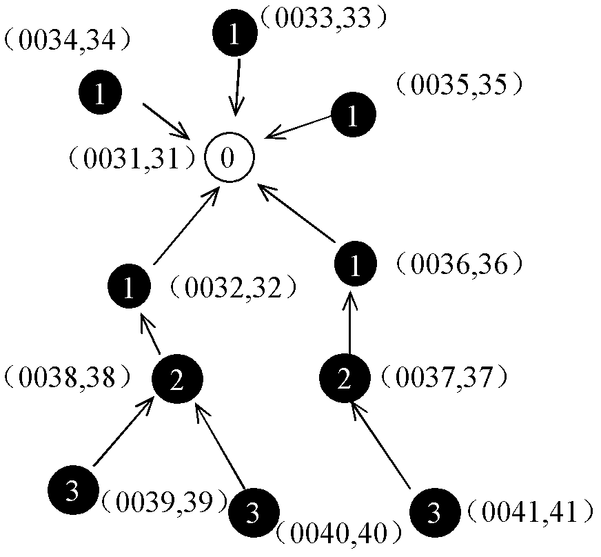
[0026] Such as image 3 As shown, this is a schematic diagram of the establishment of a multi-channel multi-hop distributed cognitive radio network. The communication frequency band is 694-806MHz, which is divided into 14 channels, and the channel numbers are from 0 to 13. The number in the middle of the circle indicates the LID of the node, and the combination of numbers indicates ; here, "○" indicates the root node, and "●" indicates the common node, such as image 3 As shown, it can be seen that the LIDs of ordinary nodes in different locations are different. The establishment process of this distributed network is as follows:

[0027] Step 1: Select a node with a node ID of 31 as the root node, and assume that the available channels locally perceived by the node are 0, 1, 3, 5, 6, 8, 10, 12, and 13. Select the strategy to determine the three channels 0, 1, and 3 as the working channels of the distributed network, enter the working state, broadcast and send Beacon messages, ...

Embodiment 2

[0041] Such as Figure 4 As shown in , it shows a schematic diagram of a late network node accessing a distributed cognitive radio network. Here, "○" means the root node, "●" means the normal node, Represents a late-entry node, assuming that the working channels of the current distributed network are 1, 2, and 3; the process of late-entry node 49 accessing the distributed network is as follows:

[0042] Step 1: the late network entry node 49 listens to the Beacon message on its perceived 0, 1, 2, 3, 5, 6, 8, 11, and 13 channels, first performs rough capture, and the time to stay on each idle channel is 300ms, here, the execution time length TC of the coarse capture is 2s.

[0043] Step 2: When the rough capture phase ends, according to the rough capture result records, the number of Beacon captured on channels 1, 2, and 3 are respectively: 120, 118, and 119, and the number on other idle channels is 0. According to the captured Beacon report Select channels 1, 2, and 3 as fi...


PUM


Abstract

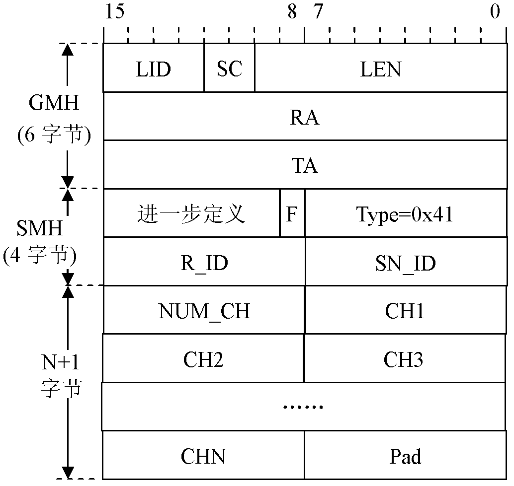
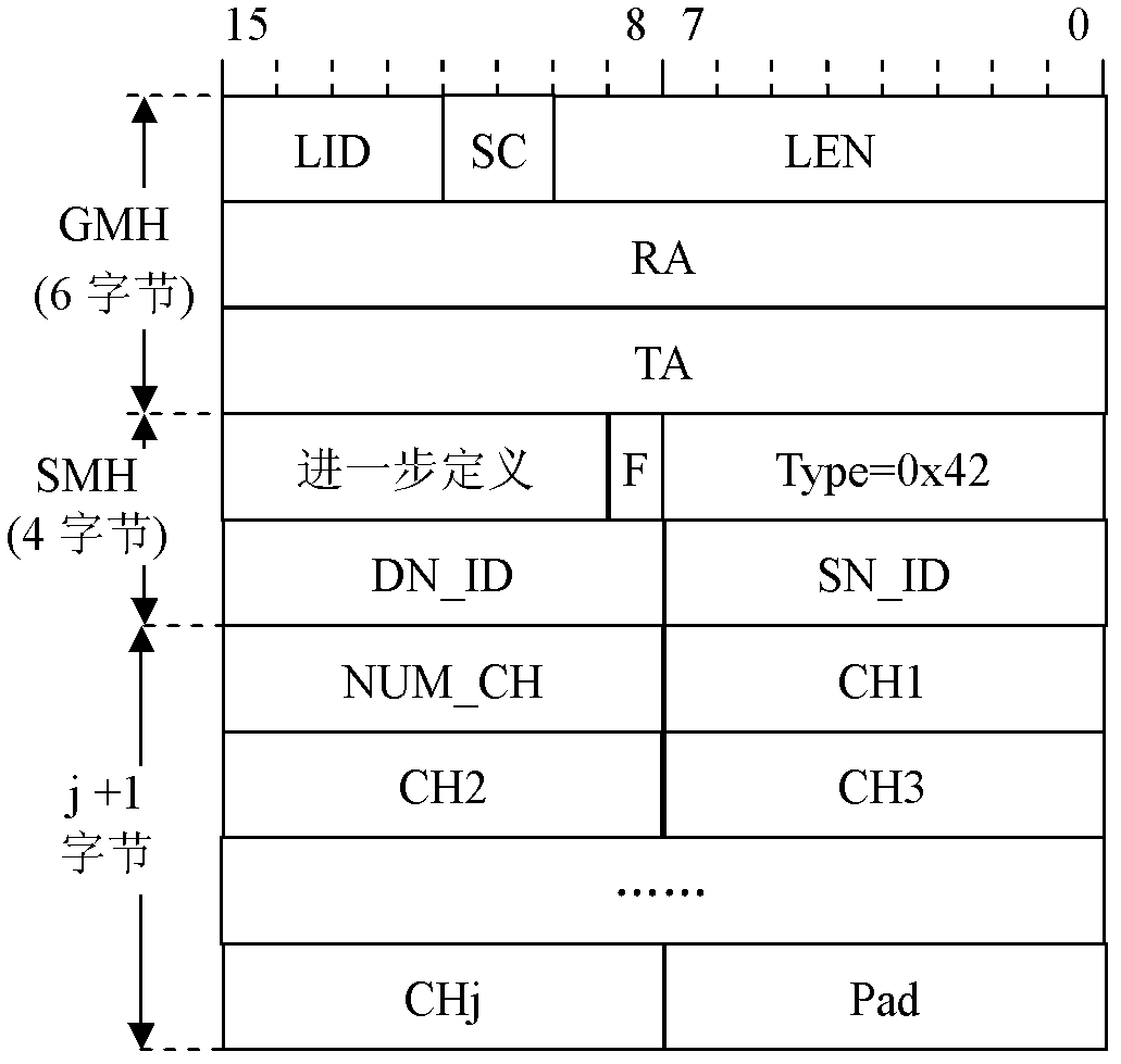
The invention belongs to wireless communication technical field, and discloses a channel initialization method for a distributed cognitive radio network. The method is characterized in that: through monitoring idle channels, N channel machines capture a Beacon message sent by a root node, and a whole monitoring process is divided into a crude capture phase and a fine capture phase, wherein a preset root node plays a dominant role in whole channel initialization, and other nodes connect with a network through capturing the Beacon message and according to a message in a notification; after connecting with the network, a common node sends an Info message to a superior node to report locally perceptive available channel information, step by step the information is gathered at the root node, thus the root node can calculate available idle channels in the whole network, and a problem of an initial networking difficulty caused by inconsistence of available channels of each node is effectively solved. According to a mechanism of periodically broadcasting Beacon messages, a network access problem of a delayed network node is effectively solved.

Description

technical field [0001] The invention belongs to the technical field of wireless communication, and in particular relates to a channel initialization method of a distributed cognitive radio network. Background technique [0002] With the development of wireless technology and the continuous growth of wireless users, wireless resources have become very scarce resources. At present, the wireless spectrum is mainly planned by the state, which leads to extreme shortage of some frequency band resources, while some frequency band resources are not fully utilized. In order to make full use of spectrum resources, a Cognitive Radio (CR, Cognitive Radio) technology is proposed to determine whether a licensed frequency band can be used for wireless communication by sensing the presence or absence of licensed users in real time. [0003] In a multi-hop distributed cognitive radio network, due to the differences in the wireless environment, the local perception spectrum information of ea...

Claims


Application Information

Patent Timeline
Patent Type & Authority Applications(China)
IPC IPC(8): H04W16/14H04W28/16
Inventor 黄晓燕申如意
Owner UNIV OF ELECTRONICS SCI & TECH OF CHINA
Learn More