Supercharge Your Innovation With Domain-Expert AI Agents!

Method of humidifying a gas stream and assembly therefor

A technology of gas flow and components, applied in the direction of drug devices, other medical devices, respirators, etc., can solve the problems of gas temperature rise, concentration, low efficiency, etc.

Inactive Publication Date: 2011-11-23
KONINK PHILIPS ELECTRONICS NV
View PDF6 Cites 0 Cited by
  • Summary
  • Abstract
  • Description
  • Claims
  • Application Information

AI Technical Summary

Problems solved by technology

Such devices are generally inefficient as part of the applied energy is usually lost to the surrounding environment and not used to heat the medium and gas
Condensation may still occur downstream of the filter as such losses place a limit on the rise in gas temperature
Furthermore, known devices often allow moisture to concentrate on the filter media

Method used


Image

  • Method of humidifying a gas stream and assembly therefor
  • Method of humidifying a gas stream and assembly therefor
  • Method of humidifying a gas stream and assembly therefor

Examples


Embodiment Construction

[0016] Directional phrases used herein, such as, but not limited to, top, bottom, left, right, up, down, front, back, and derivatives thereof, refer to the orientation of elements shown in the drawings and do not limit the claims, unless expressly stated therein.

[0017] As used herein, the expression that two or more parts or components are "coupled" together shall mean that the parts are joined or work together either directly or through one or more intermediate parts or components.

[0018] As used herein, the term "amount" means one or an integer greater than one (ie, a plural number).

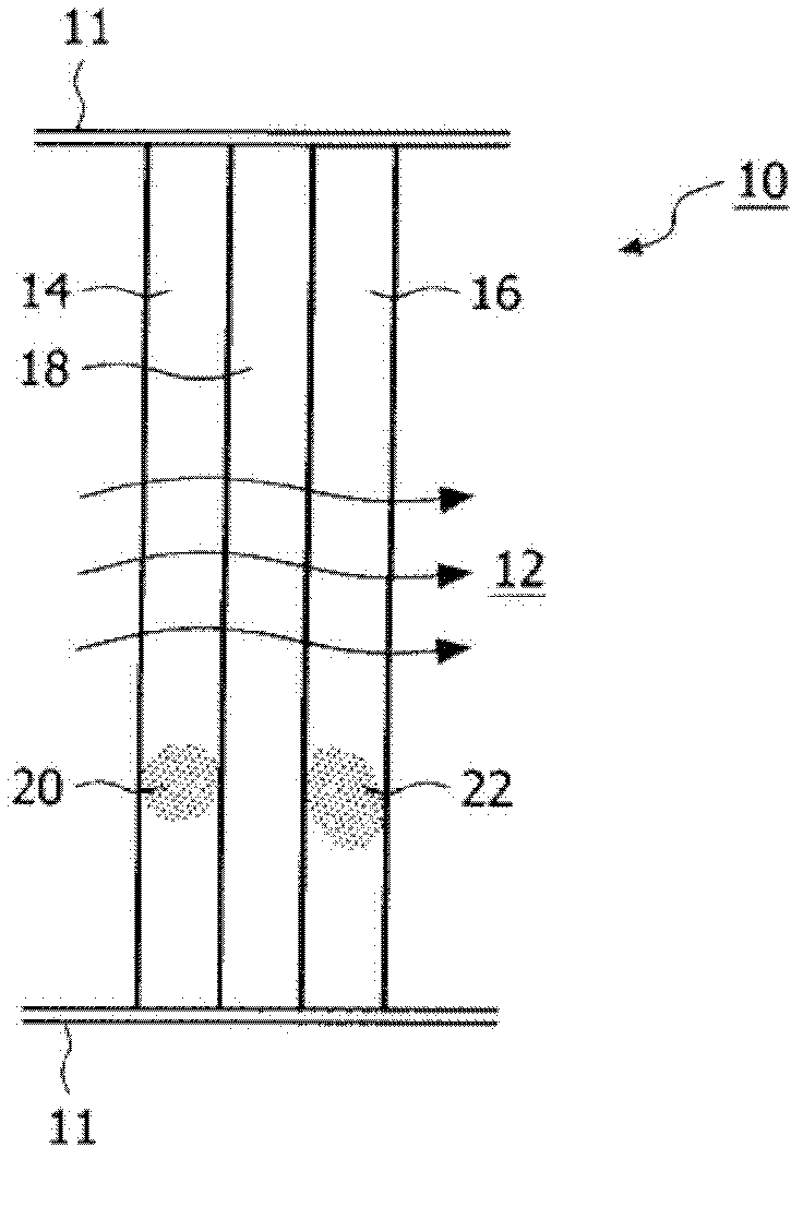
[0019] figure 1 A cross-sectional view of a filter assembly 10 according to an embodiment of the invention is shown. Filter assembly 10 is housed within conduit 11 or other suitable structure (eg, but not limited to, rigid plastic housing, flexible or rigid tubing) to direct gas flow 12 therethrough. Gas flow 12 may include, for example and without limitation, inhaled gas for use by a ...


PUM


Abstract

The present invention provides a humidifier assembly for humidifying a gas stream. The humidifier assembly including a heating element structured to be disposed in the gas stream for directly heating the gas stream as the gas stream passes therethrough and a supply of fluid provided at or near the heating element.

Description

technical field [0001] The present invention relates generally to humidifier assemblies for humidifying a gas stream, and more particularly, to humidifier assemblies with integrated heat sources. The invention also relates to a method of humidifying a gas stream. Background technique [0002] The high incidence of and awareness of airborne disease (eg, SARS, avian influenza) requires filtration of a patient's exhaled air during mechanical ventilation in some healthcare settings. Exhaled air typically arrives at the respirator unit at a temperature of 37C and a relative humidity close to 100%. Therefore, in-line filters used in such applications need to be able to withstand the effects of moisture. Administering an inline aerosol drug may also cause the filter element to be affected similarly to when it encounters moisture. Wet filter elements may weaken and cause rupture of the filter media within such filter elements. Wet filter elements also have a higher flow resistan...

Claims


Application Information

Patent Timeline
Patent Type & Authority Applications(China)
IPC IPC(8): A61M16/16
CPCA61M16/16A61M16/105A61M2205/7527A61M16/147
Inventor G·基姆M·阿希利亚
Owner KONINK PHILIPS ELECTRONICS NV
Features
  • R&D
  • Intellectual Property
  • Life Sciences
  • Materials
  • Tech Scout
  • Unparalleled Data Quality
  • Higher Quality Content
  • 60% Fewer Hallucinations
Learn More