
A rope braking and descending device and a rope threading method

A rope and control handle technology, applied in life-saving equipment, building rescue, etc., can solve accidents, increase difficulty and other problems, and achieve the effects of avoiding safety accidents, high safety, and convenient and simple use

Active Publication Date: 2011-11-30
FUJIAN DONGSHAN COUNTY HUIYONGTAI SPORTS GOODS
View PDF5 Cites 13 Cited by
  • Summary
  • Abstract
  • Description
  • Claims
  • Application Information

AI Technical Summary

Problems solved by technology

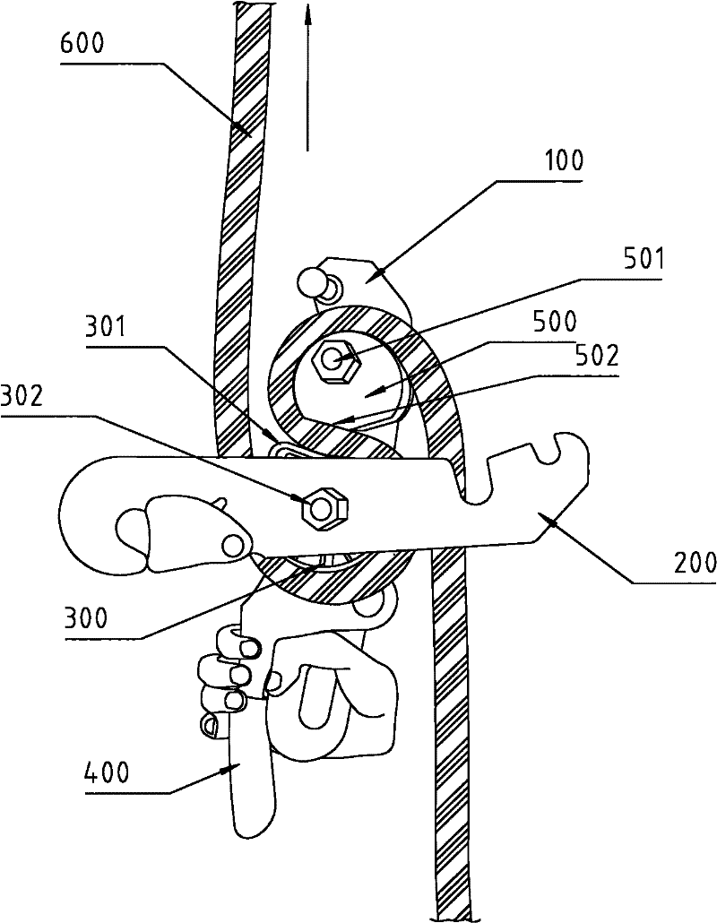
However, according to the structure of the existing descender, if the control handle 400 is held tightly, the rope 600 will pass through the descender more quickly, and the result is self-evident
[0004] Additionally, from figure 1 It can also be seen that when the existing descender is in use, the winding of the descending rope 600 also has strict and unique regulations, that is, the protruding part 301 of the movable wheel 300 goes around the movable wheel 300 downwards and then goes upward. Then bypass the fixed wheel 500; on the contrary, if the user has not undergone strict training or neglects to wind the descending rope in the opposite direction, the friction force between the rope 600 and the movable wheel 300 will not automatically stop the rope during the descent. , on the contrary, it will increase the difficulty of man-made stop, and the possibility of accidents will be greatly increased.

Method used


Image

  • A rope braking and descending device and a rope threading method
  • A rope braking and descending device and a rope threading method
  • A rope braking and descending device and a rope threading method

Examples


Embodiment Construction

[0035] Embodiments of the present invention will be described in detail below in conjunction with the accompanying drawings.

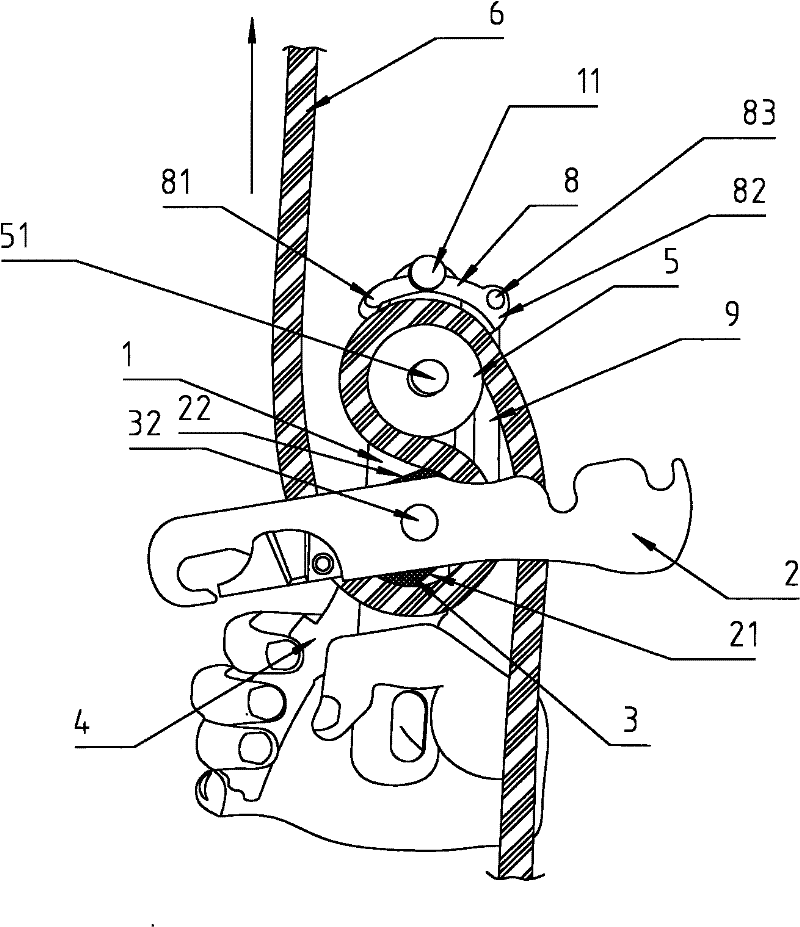
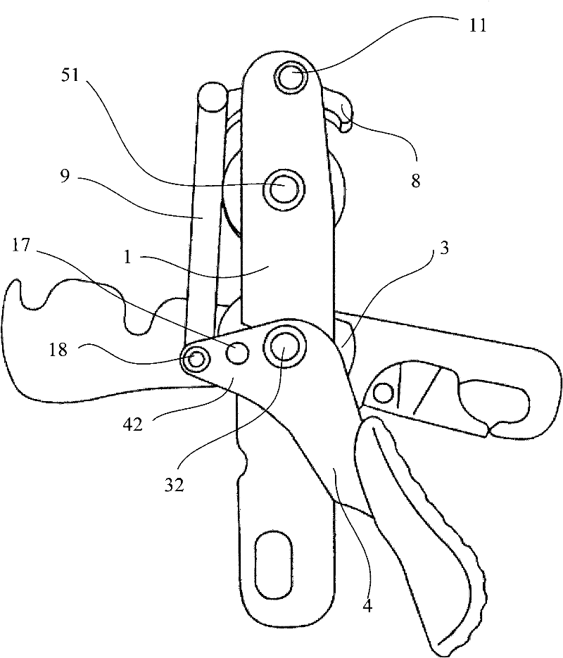
[0036] like figure 2 , image 3 As shown, a rope braking descender provided by the present invention includes a fixed side plate 1 and a movable side plate 2 that is rotatably connected to the fixed side plate 1 through a first pin shaft 32, and on the first pin shaft 32 A movable wheel 3 with a groove (not shown) on the outer periphery that can rotate with the movement of the rope and a control handle 4 are sleeved, and the movable wheel 3 is located on the fixed side plate 1 and the movable side plate 2 Between, the control handle 4 is linked with the movable wheel 3; the fixed side plate 1 on the upper part of the movable wheel 3 is fixedly provided with a fixed wheel 5 with a groove on the outer periphery through the second pin shaft 51; , the fixed side plate 1 on the upper part of the fixed wheel 5 is connected with a bow-shaped stop plate 8 t...


PUM


Abstract

The invention discloses a rope brake descender. The descender comprises a fixed side board, a movable side board, a movable wheel disk and a control handle, wherein, the fixed side board is rotationally connected with the movable side board through a first pin shaft; a fixed wheel disk is fixedly arranged on the fixed side board at the upper part of the movable wheel disk through a second pin shaft; an arched brake swinging sheet is rotationally connected on the fixed side board at the upper part of the fixed wheel disk through a third pin shaft; a connecting arm is arranged on a connecting end of the control handle and the first pin shaft; and the end part of the connecting arm and the corresponding end of the brake swinging sheet are respectively hinged on two ends of a connecting rod so that the connecting rod drives the brake swinging sheet to rotate back and forth around the third pin shaft and meanwhile one of two ends of the brake swinging sheet abuts against the periphery of the fixed wheel disk as the control handle swings back and forth. The rope brake descender has the characteristics of reasonable design and high safety, and is practical and convenient.

Description

technical field [0001] The invention relates to a high-altitude slow descending device, in particular to a rope braking descending device. It can be applied to outdoor sports, fire rescue, military rescue, high-altitude operations, etc. The invention also relates to the rope threading method of the rope braking descender. Background technique [0002] figure 1 Shown is an existing common descender, which includes a fixed side plate 100 and a movable side plate 200 that is rotatably connected to the fixed side plate 100 through a first pin shaft 302, and a movable side plate is sleeved on the first pin shaft 302. Wheel 300 and a control handle 400, the eccentric cam 300 is located between the fixed side plate 100 and the movable side plate 200, the control handle 400 is located between the fixed side plate 100 and the movable wheel 300 between, and, the control handle 400 is linked with the movable wheel 300; the fixed side plate 100 on the upper part of the movable wheel ...

Claims


Application Information

Patent Timeline
Patent Type & Authority Applications(China)
IPC IPC(8): A62B1/14
Inventor 刘文辉
Owner FUJIAN DONGSHAN COUNTY HUIYONGTAI SPORTS GOODS
Learn More