Brushless direct-current motor power converter

A brush DC motor and power converter technology, which is applied in the direction of conversion equipment without intermediate conversion to AC, torque ripple control, etc., can solve problems such as large torque ripple of brushless DC motors, and achieve rapid bus voltage adjustment and control The effect of convenience and simple circuit structure

Active Publication Date: 2013-12-04
NANJING UNIV OF AERONAUTICS & ASTRONAUTICS
View PDF4 Cites 5 Cited by
  • Summary
  • Abstract
  • Description
  • Claims
  • Application Information

AI Technical Summary

Problems solved by technology

[0004] The technical problem to be solved by the present invention is: to propose a brushless DC

Method used


Image

  • Brushless direct-current motor power converter
  • Brushless direct-current motor power converter
  • Brushless direct-current motor power converter

Examples


Example Embodiment

[0024] The technical solution of the present invention will be described in detail below in conjunction with the drawings:

[0025] Taking the power switch tubes I, II, and III as MOS tubes as an example, the technical solution will be explained in detail:

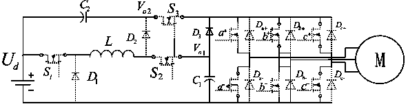
[0026] A brushless DC motor power converter, which is characterized in that it includes a DC power supply, capacitor I, capacitor II, switch tube I, switch tube II, switch tube III, diode I, diode II, diode III, inductor L, three-phase Inverter bridge; wherein the anode of the DC power supply is connected to the cathode of the capacitor II and the input end of the switch tube I; the anode of the capacitor II is connected to the cathode of the diode II and the input end of the switch tube III respectively; the switch The output end of the tube III is respectively connected to the cathode of the diode III and the anode of the input terminal of the three-phase inverter bridge; the output end of the switch tube I is respectively co...


PUM


Abstract

The invention discloses a brushless direct-current motor power converter which comprises a direct-current power source, a capacitor I, a capacitor II, a switching tube I, a switching tube II, a switching tube III, a diode I, a diode II, a diode III, an inductor and a three-phase bridge inverter. In a switching period, energy is stored in the inductor, the energy in the inductor is enabled to flow towards the two capacitors by controlling the switching tubes respectively, and the amount of the energy flowing towards the capacitors is controlled by controlling duty ratios of the switching tubes to realize voltage boosting and voltage reducing. Supply voltage on a brushless direct-current motor can be quickly changed by a selector switch. The brushless direct-current motor power converter is few in power device and simple in structure, torque pulsation of the brushless direct-current motor is inhibited, and dynamic response speed is increased.

Description

technical field [0001] The invention relates to a power converter, more specifically, to a brushless DC motor power converter. Background technique [0002] In recent years, brushless DC motors have been used more and more widely because of their advantages such as high power density, superior speed regulation performance, and simple control. However, its inherent disadvantage of large commutation torque ripple limits its application in low torque ripple, low noise and high precision speed regulation systems. In order to suppress the commutation torque ripple of brushless DC motors, many methods have been proposed, such as current chopping method, overlapping commutation method, direct torque control, etc., but starting from the control strategy, it can only be controlled in a specific speed range. The commutation torque ripple cannot be suppressed within the full speed range. [0003] In the prior art, brushless DC motors are generally controlled by a three-phase inverter...

Claims


Application Information

Patent Timeline
IPC IPC(8): H02M3/07H02P6/10
Inventor 盛田田王晓琳
Owner NANJING UNIV OF AERONAUTICS & ASTRONAUTICS
Why Eureka
Try Eureka