Bending machine for braking hose coupler

A brake hose and bending machine technology, applied in the field of bending machines, can solve problems affecting quality, pin chamfer asymmetry, cutting, etc., to avoid extrusion deformation or cutting, ensure bending angle, and accurate positioning Effect

Inactive Publication Date: 2013-03-20
宁波名古屋工业有限公司
View PDF4 Cites 0 Cited by
  • Summary
  • Abstract
  • Description
  • Claims
  • Application Information

AI Technical Summary

Problems solved by technology

[0003] The brake hose joint bending machine of the above prior art has the following disadvantages: because the roller is in direct contact with the pin when it works, and the roller moves by strong air pressure, so when bending, the part of the pin in contact with the roller is extremely It may be squeezed and deformed by a strong impact force, or even cut off a part, which will make the chamfer of the pin asymmetrical and affect the quality; and because the pin is not well positioned during bending, the bending angle of the pin will be caused. There are errors, which directly affect the quality

Method used


Image

  • Bending machine for braking hose coupler
  • Bending machine for braking hose coupler
  • Bending machine for braking hose coupler

Examples


Embodiment Construction

[0019] The brake hose joint bending machine of the present invention will be further described below in conjunction with the accompanying drawings.

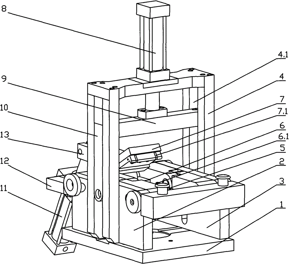
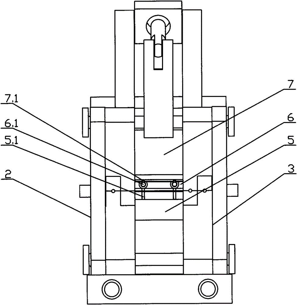
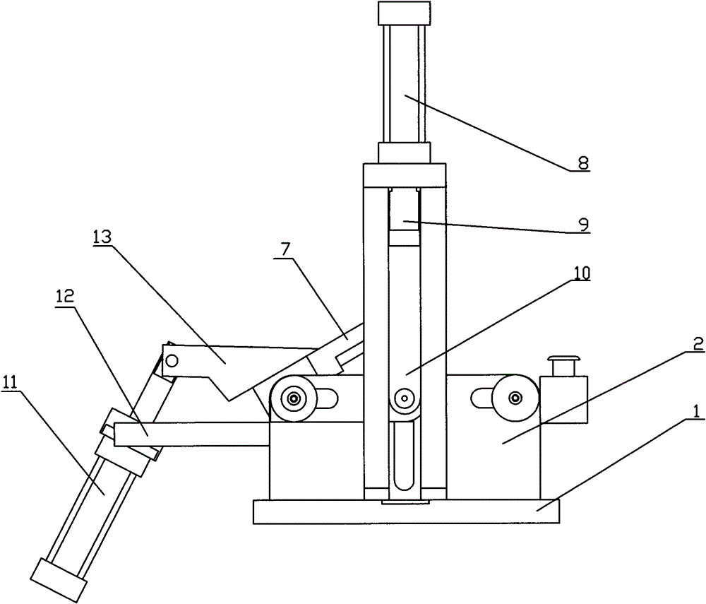
[0020] like figure 1 , figure 2 , image 3 , Figure 4 , Figure 5 As shown, the brake hose joint bending machine of the present invention includes a base 1, a left fixed plate 2, a right fixed plate 3, a support frame 4, a first movable mold 5, a second movable mold 6, and a third movable mold 7. The left fixed plate 2, the right fixed plate 3 and the support plate 4 are all fixed on the base 1, and the first movable mold 5 and the second movable mold 6 are all arranged on the left fixed plate 2 and the right fixed plate 3 And between the left fixed plate 2 and the right fixed plate 3, one side of the first movable mold 5 and the second movable mold 6 are hinged together, and the hinge shaft is slidingly fitted in the guide grooves on both sides of the support frame 4 In 4.1, the support frame 4 is also provided with a pre...


PUM


Abstract

The invention discloses a bending machine for a braking hose coupler. The bending machine comprises a base (1), a left fixed plate (2), a right fixed plate (3), a support frame (4), a first movable die (5), a second movable die (6), a third movable die (7), wherein the left fixed plate (2), the right fixed plate (3) and the support frame (4) are fixed to the base (1); the first movable die (5) and the second movable die (6) are arranged on the left fixed plate (2) and the right fixed plate (3) and are positioned between the left fixed plate (2) and the right fixed plate (3); the first movabledie (5) is hinged with one side of the second movable die (6); a pressing mechanism which is fixed with a hinged shaft is also arranged on the support frame (4); and the third movable die (7) is hinged with the other side of the second movable die (6). By the bending machine for the braking hose coupler, pins of the braking hose coupler can be prevented from being extruded or cut, and the bendingangles of the pins can be ensured.

Description

technical field [0001] The invention relates to a bending machine, in particular to a brake hose joint bending machine. Background technique [0002] The front end of the brake hose connector on the market is generally provided with a positioning pin. In order to better fix the brake hose connector, the positioning pin needs to be bent to 90 degrees, which requires special equipment for processing. The currently used brake hose joint bending machine mainly relies on the rollers on the movable mold to process the pins. When working, put the product on the movable lower mold. After starting the switch, the upper mold presses down to fix the product. The movable mold works to drive the roller. The roller moves from top to bottom. After contacting the pin, it continues downward and the pin The contact part is bent downward. [0003] The brake hose joint bending machine of the above prior art has the following disadvantages: because the roller is in direct contact with the pin ...

Claims


Application Information

Patent Timeline
Patent Type & Authority Patents(China)
IPC IPC(8): B21D7/024
Inventor 董阿能郑志军
Owner 宁波名古屋工业有限公司
Why Eureka
Try Eureka