Material deformation measurement method and device based on laser marking automatic tracking

A technology of laser marking and automatic tracking, which is applied in the direction of measuring devices, optical devices, instruments, etc., can solve the problems of reduced measurement accuracy and deformation of sample marking lines, and achieve the effects of high measurement accuracy, simple structure, and easy practicality

Inactive Publication Date: 2011-11-30
ZHEJIANG SCI-TECH UNIV
View PDF5 Cites 16 Cited by
  • Summary
  • Abstract
  • Description
  • Claims
  • Application Information

AI Technical Summary

Benefits of technology

This technology allows for precise measurements without damaging or affecting any part of it by capturing full 360 degrees of shape change with an optically focused camera system. By measuring changes caused by this movement, we have improved precision compared to previous methods such as touch tonometers. Additionally, there's no issue where the sensor becomes blocked due to its placement close enough together when trying to track small areas around sharp edges like screw threads. Overall, these technical improvements make our use of lasers more efficient than older techniques while maintaining their benefits.

Problems solved by technology

This patented describes different ways to measure material's physical characteristics such as stress, expansion/contraction, etc., while ensuring consistently high quality measurements over long periods (severs) due to factors like wear and tear caused by repeated flexion motion. Current methods involve measuring these changes with expensive equipment and require manual intervention. Non-contact techniques have been developed but they still suffer from issues related to their reliance upon precise placement of markers onto test specimens.

Method used


Image

  • Material deformation measurement method and device based on laser marking automatic tracking
  • Material deformation measurement method and device based on laser marking automatic tracking
  • Material deformation measurement method and device based on laser marking automatic tracking

Examples


Embodiment Construction

[0017] The present invention will be further described below in conjunction with the accompanying drawings and specific embodiments.

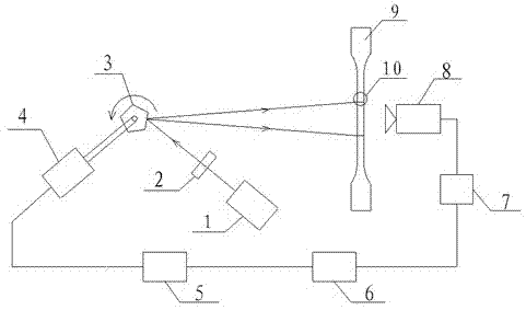
[0018] The laser beam of the laser device 1 of the present invention passes through the laser mark formed after the reticle 2, and is reflected on the sample mark line 10 of the sample 9 through the pentagonal prism 3, so that the laser mark coincides with the sample mark line 10; the motor controller One end of 5 controls the servo motor 4 to drive the pentagonal prism 3 to rotate, and the other end of the motor controller 5 is connected to the CCD8 through the computer 6 and the image acquisition card 7, and the CCD8 collects the images of the laser marking and the sample marking line 10 in real time, and through image acquisition The card 7 is input into the computer 6 to obtain the deformation amount of the sample.

[0019] Material deformation measurement method and device based on laser marking automatic tracking, such as figure 1 As sho...


PUM


Abstract

The invention discloses a method and a device for measuring material deformation based on automatic tracking of laser marks. According to the method, laser output by a laser passes through a division plate to form laser marks with different patterns, is ejected to a pentagonal prism and irradiated on a mark line of a material to be tested (namely a sample) after being reflected by the pentagonal prism; a servo motor and a motor controller drive the pentagonal prism to rotate, so that laser marks automatically track the changes of the sample mark line during deformation of the material; imagesof the laser marks and the sample mark line are acquired by a charge coupled device (CCD) in real time and input to a computer; and the deformation of the sample is obtained after digital image processing. The device has high anti-interference capability, and is low in cost and easy for practical application. Moreover, the measurement precision of the material deformation can reach over 0.02 percent.

Description


Claims


Application Information

Patent Timeline
Owner ZHEJIANG SCI-TECH UNIV
Why Eureka
Try Eureka