Crank Shaft Vibrating Screen

A technology of oscillating screen and crankshaft, applied in screen, solid separation, grille, etc., can solve the problems of unsuitable workload, low work efficiency, complex machine structure, etc., to reduce equipment cost, improve work capacity, and simplify equipment effect of structure

Inactive Publication Date: 2011-12-07
INST OF AGRO FOOD SCI & TECH SHANDONG ACAD OF AGRI SCI
View PDF6 Cites 10 Cited by
  • Summary
  • Abstract
  • Description
  • Claims
  • Application Information

AI Technical Summary

Problems solved by technology

[0002] Most of the current vibrating screens are reciprocating eccentric connecting rod vibrating screens. When working, a motor drives two eccentric connecting rods to move the screen mesh longitudinally, thereb...

Method used


Image

  • Crank Shaft Vibrating Screen
  • Crank Shaft Vibrating Screen
  • Crank Shaft Vibrating Screen

Examples


Embodiment Construction

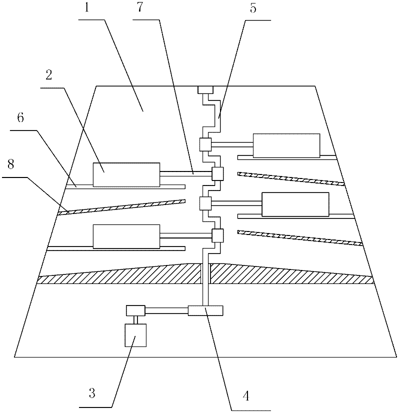
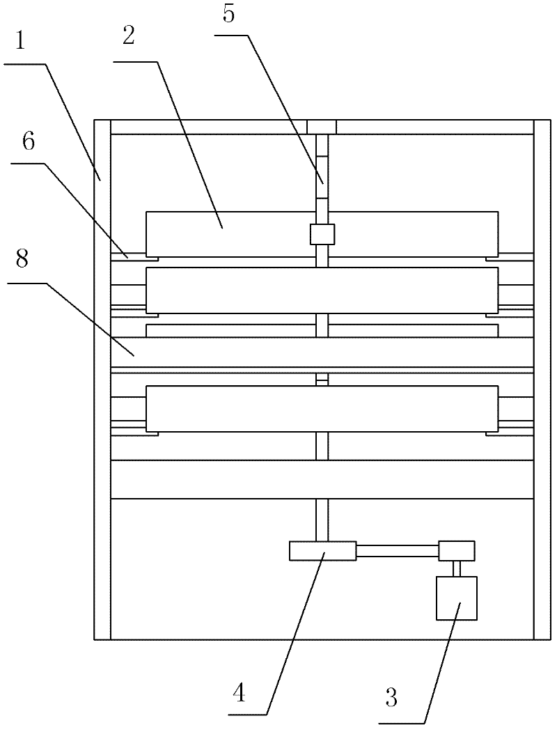
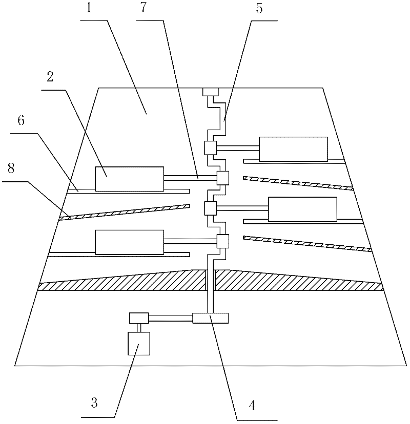
[0009] Such as figure 1 , figure 2 As shown, the crankshaft vibrating screen includes a frame 1 and a vibrating screen 2. A motor 3 is arranged below the frame 1, and a pulley 4 is fixed at the output end of the motor 3. The pulley 4 is fixed at the end of the crankshaft 5, and the crankshaft 5 The other end of the frame is fixed on the top of the frame 1 through a bearing; the frame 1 is provided with a multi-layer slideway 6 along the vertical direction, the vibrating screen 2 is fixed on the frame 1 through the slideway 6, and one end of the vibrating screen 2 is fixed There is a connecting rod 7, the other end of the connecting rod 7 is fixed on the crankshaft 5 through a bearing, and an inclined blanking baffle 8 is provided below the vibrating screen 2, and both sides of the lower baffle 8 are fixed on the frame 1 .

[0010] Connect the power supply to make the motor 3 rotate, drive the crankshaft 5 to rotate through the pulley 4, and drive each layer of vibrating scr...


PUM


Abstract

A crankshaft type vibrating screen relates to a vibrating screen, which solves the problem of low working efficiency of the traditional vibrating screen and complicated machine configuration. Including a frame and a vibrating screen, a motor is arranged under the frame, a pulley is fixed at the output end of the motor, the pulley is fixed at the end of the crankshaft, and the other end of the crankshaft is fixed on the top of the frame through a bearing; the frame There is a multi-layer slideway along the vertical direction, and a vibrating screen is placed on the slideway. One end of the vibrating screen is fixed with a connecting rod, and the other end of the connecting rod is fixed on the crankshaft through a bearing. The baffle, the both sides of the lower baffle are fixed on the frame. The invention drives the multi-layer vibrating screen through the crankshaft, improves the working capacity, improves the working efficiency, simplifies the equipment structure and reduces the equipment cost.

Description

technical field [0001] The invention relates to an oscillating screen, in particular to a crankshaft type oscillating screen. Background technique [0002] Most of the current vibrating screens are reciprocating eccentric connecting rod vibrating screens. When working, a motor drives two eccentric connecting rods to move the screen mesh longitudinally, thereby completing the material screening operation, but the eccentric connecting rod vibrating screen Both are single screens, with low working efficiency and complex machine structure, which is not suitable for heavy workload. Contents of the invention [0003] The object of the present invention is to provide a crankshaft type vibrating screen to solve the above problems. [0004] The technical solution adopted by the present invention to solve its technical problems is: a crankshaft type vibrating screen, comprising a frame and a vibrating screen, characterized in that a motor is arranged below the frame, and a pulley i...

Claims


Application Information

Patent Timeline
IPC IPC(8): B07B1/28B07B1/42
Inventor 宋康王红日汝医阴卫军王宪昌
Owner INST OF AGRO FOOD SCI & TECH SHANDONG ACAD OF AGRI SCI
Why Eureka
Try Eureka