Dual light source medical lighting device

A lighting device and dual light source technology, applied in the field of medical lighting, can solve the problems that no effective solution has been proposed, the deep surgical lamp does not reduce the shadow, and the function of deep cavity lighting cannot be achieved.

Inactive Publication Date: 2011-12-07
BEIJING AEONMED
View PDF2 Cites 6 Cited by
  • Summary
  • Abstract
  • Description
  • Claims
  • Application Information

AI Technical Summary

Problems solved by technology

[0004] The disadvantage of using a single light source as a whole reflective medical lighting equipment is that since there is only one reflector and one light source, all the illumination light is reflected from one reflector by the light source, and there is only one illuminated surface of the reflector, which cannot provide an ideal The spatial area with the same illuminance, color rendering index, and color temperature cannot provide ideal lighting for the deep cavity during deep cavity surgery, which will affect the progress of medical activities.
[0005] At present, the most ideal lighting for the deep cavity is the deep surgical light, but the deep surgical lamp has no function of weakening the shadow, and when performing medical activities (surgery) that need to weaken the shadow function, the deep surgical lamp cannot be placed above the surgical wound , otherwise it will interfere with the medical lighting equipment that provides the function of reducing shadows, and if it is biased to the side of the wound, it will not be able to perform the function of deep cavity lighting
[0006] In the technology of related medical lighting methods, no effective solution has been proposed in terms of compatibility with reduced shadow lighting and deep cavity lighting

Method used


Image

  • Dual light source medical lighting device
  • Dual light source medical lighting device
  • Dual light source medical lighting device

Examples


Embodiment Construction

[0024] The embodiments of the present invention will be described in detail below with reference to the accompanying drawings, but the present invention can be implemented in many different ways defined and covered by the claims.

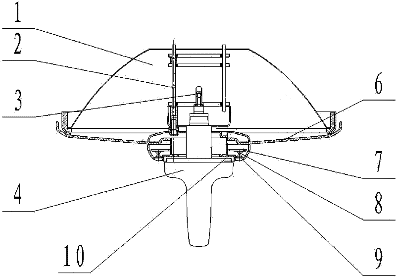
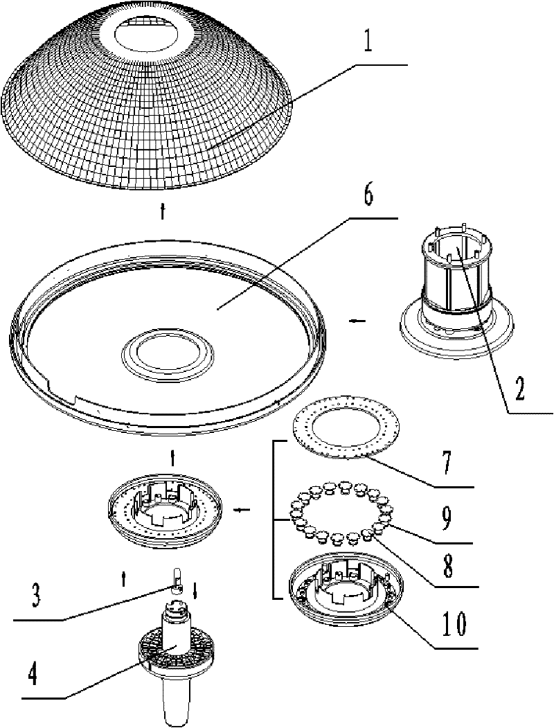
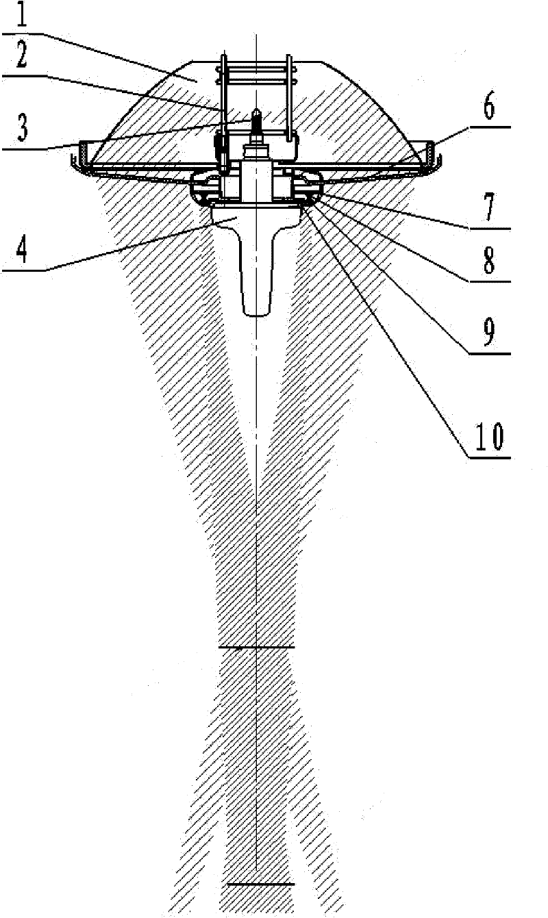
[0025] Such as figure 1 As shown, in one embodiment of the present invention, the dual-light source medical lighting device includes: a spherical reflector 1 ; and a first light source 3 and a second light source arranged in front of the spherical reflector 1 . The first light source 3 gathers the light emitted by the first light source toward the target position through the reflection of the reflector 1; the second light source is located on the side of the first light source away from the reflector, and projects parallel light beams toward the target position. In this structure, the light emitted by the first light source is reflected by the spherical reflector and irradiated from different directions to the target position (surgical wound) for co...


PUM


Abstract

The invention discloses a medical illuminating device with dual light sources, which comprises: a spherical reflector; a first light source is arranged in front of the reflector, and the light emitted by the first light is gathered toward a target position by reflection of the reflector; a second light source , is arranged in front of the reflector, and is located on a side of the first light source away from the reflector, and projects a parallel light beam toward a target position. The dual-light source medical lighting device provided by the present invention irradiates the filtered light of the first light source to the surgical wound from different directions by using a spherical reflector to complete the lighting function of weakening the shadow of the illuminated object. The light beam emitted by the second light source at the center of the medical lighting equipment is projected to the deep part of the surgical wound to complete the lighting function of deep cavity lighting. Combining two light sources with different lighting functions into one effectively solves the problem of incompatibility between lighting for weakening shadows and lighting for deep cavities in existing medical lighting methods.

Description

technical field [0001] The invention relates to the field of medical lighting, in particular to a dual light source medical lighting device. Background technique [0002] In the medical activities carried out, according to the functions of medical lighting equipment, medical lighting equipment is divided into shadowless lamps, deep lamps, diagnostic lights and other types. Specific to surgical treatment activities in medical activities, lighting equipment must not only weaken the light exposure The function of the shadow of the object, and the lighting to be provided must have a certain lighting depth (the high illuminance requirement per unit area must be met within a certain range of up and down distances from the irradiation plane), so there are shadowless lamps and deep lights used in medical lighting equipment Lighting lighting equipment. [0003] At present, in the lighting equipment used for medical activities (surgery), most of them use single light source overall r...

Claims


Application Information

Patent Timeline
Patent Type & Authority Applications(China)
IPC IPC(8): F21S2/00F21V7/00F21V9/10F21V5/04F21V17/00F21W131/20F21V9/40
Inventor 陆银发刘倩吴梁尹海文
Owner BEIJING AEONMED
Why Eureka
Try Eureka