Eureka AIR delivers breakthrough ideas for toughest innovation challenges, trusted by R&D personnel around the world.

display device

A display device and display panel technology, applied in identification devices, static indicators, instruments, etc., can solve problems such as yield problems, signal quality impact, and manufacturing difficulties

Inactive Publication Date: 2011-12-07
HUAYING OPTOELECTRONICS +1
View PDF1 Cites 18 Cited by
  • Summary
  • Abstract
  • Description
  • Claims
  • Application Information

AI Technical Summary

Problems solved by technology

And when the width of the signal traces is designed too narrow (easy to overheat, and may be difficult to manufacture and have yield problems), or when the signal traces are too close to each other (mutual interference of electrical signal transmission), it may also affect the signal traces. The quality of the signal transmitted by the line is seriously affected

Method used


Image

  • display device
  • display device
  • display device

Examples


Embodiment Construction

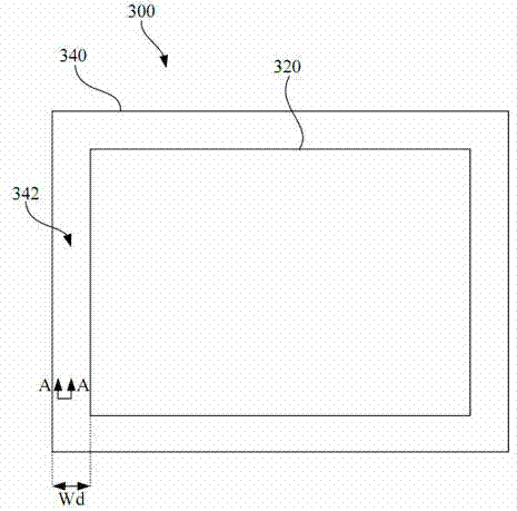
[0036] see figure 2 , which shows a schematic diagram of a display device 300 according to an embodiment of the disclosure, as figure 2 As shown, the display device 300 includes a display panel 320 and a frame 340 .

[0037] This publication discloses the design of the signal routing on the frame 340 of the display device 300 . In this embodiment, the frame area 342 on the left side of the display panel 320 is used as an example for illustration, but the present invention is not limited to the left side of the display panel 320 .

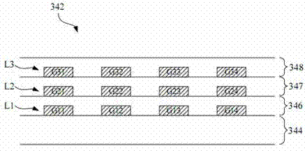
[0038] Please also refer to image 3 , which is shown in an example figure 2 A schematic cross-sectional structure diagram of the middle frame region 342 along the section line A-A. Such as image 3 As shown, in practical applications, the bottom of the frame area 342 may be the substrate 344 , and the first insulating layer 346 , the second insulating layer 347 and the third insulating layer 348 are sequentially disposed on the substrate 34...


PUM


Abstract

The invention discloses a display device, which includes a display panel, a first signal wiring layer, a second signal wiring layer and a third signal wiring layer. Wherein, the first signal wiring layer, the second signal wiring layer and the third signal wiring layer are arranged in a frame area around the display panel. Moreover, the first signal routing layer, the second signal routing layer and the third signal routing layer are respectively located at different levels. Wherein the first signal wiring layer, the second signal wiring layer and the third signal wiring layer are used for transmitting control signals to the display panel.

Description

technical field [0001] The present invention relates to a display device, and in particular to a display device and its signal routing design. Background technique [0002] In the current market, liquid crystal displays are widely used in computer screens, mobile phones, personal digital assistants (PDAs), tablet computers, e-books, flat-screen TVs, etc. on electronic products. [0003] The working principle of the liquid crystal display is to change the alignment state of the liquid crystal molecules in the liquid crystal layer by changing the voltage difference between the two ends of the liquid crystal layer to change the light transmittance of the liquid crystal layer, and then cooperate with the light source provided by the backlight module to display images. Generally speaking, a display device includes a display area where a display panel is disposed and a surrounding frame area. Currently, the driving circuits of display panels are mostly divided into source driver...

Claims


Application Information

Patent Timeline
Patent Type & Authority Applications(China)
IPC IPC(8): G09F9/30G09G3/20
Inventor 江佳铭
Owner HUAYING OPTOELECTRONICS
Why Eureka
Eureka Blog
Learn More