
Manufacturing method of semiconductor element and corresponding semiconductor element

A technology for semiconductors and components, which is applied in the manufacture of semiconductor components and the field of corresponding semiconductor components, can solve problems such as multi-space, and achieve the effect of preventing environmental impact and pollution

Inactive Publication Date: 2011-12-07
ROBERT BOSCH GMBH
View PDF4 Cites 3 Cited by
  • Summary
  • Abstract
  • Description
  • Claims
  • Application Information

AI Technical Summary

Problems solved by technology

In addition, more space is required in the encapsulation process for wire connections

Method used


Image

  • Manufacturing method of semiconductor element and corresponding semiconductor element
  • Manufacturing method of semiconductor element and corresponding semiconductor element
  • Manufacturing method of semiconductor element and corresponding semiconductor element

Examples


Embodiment Construction

[0020] In these figures, the same reference numerals designate the same components, or designate functionally identical components.

[0021] figure 1 A cross-sectional view of a first process stage of a manufacturing method according to a preferred embodiment of the invention is shown.

[0022] According to this preferred embodiment of the invention, the adhesive layer 12 is first applied to the carrier plate 10 . This adhesive layer 12 is arranged in such a way that it can be detached without residue. figure 1 A carrier plate 10 with an applied adhesive layer 12 is shown.

[0023] figure 2 A cross-sectional view of a second process stage of the manufacturing method according to a preferred embodiment of the invention is shown.

[0024] According to this preferred exemplary embodiment, the copper film 14 is fastened to the carrier plate 10 by means of an adhesive layer 12 . The support plate 10 preferably has the shape of a wafer, but can also be manufactured in other fo...


PUM


Abstract

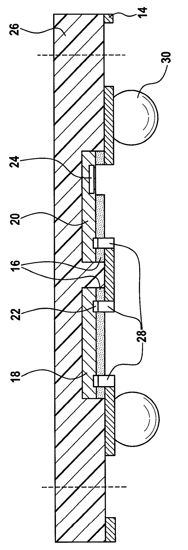
A method for producing semiconductor components and a component obtainable by such a method is disclosed. The method comprises the following steps: fixing a conductive film on a carrier; adhesively bonding semiconductor chips onto the conductive film using an adhesive layer, wherein active surfaces of the semiconductor chips, the active surfaces having connection contacts, are situated on that side of the chips which faces the film; overmolding the chips adhesively bonded onto the conductive film with a molding compound; and releasing the conductive film with the overmolded chips from the carrier. In this case, the adhesive layer is structured in such a way that at least connection contacts of the semiconductor chips are free of the adhesive layer and are kept free of the molding compound.

Description

technical field [0001] The present invention relates to a method of manufacturing a semiconductor element and a semiconductor element obtained by such a method. Background technique [0002] In terminal consumer electronics products (Consumer Electronics: CE), the microelectronic components (Integrated Circuit: IC) of the primary assembly are usually arranged side by side or overlapped on the support part (Quard Flat Pack WO Lead: QFN), or laminated plastic On the substrate (Leadless Grid Array: LGA, or Ball Gird Array: BGA), and contacted by wire connection or flip-chip technology. After mounting the chip, the carrier or the laminated plastic matrix is ​​injection-molded with a molding compound, also known as molded plastic, and separated by means of a saw. These devices are soldered to a secondary printed circuit board using a reflow soldering method. [0003] The "leadless" housings, such as LGA or QFN, are increasingly replacing conventional housings with plugs, such a...

Claims


Application Information

Patent Timeline
Patent Type & Authority Applications(China)
IPC IPC(8): H01L21/60H01L21/56H01L23/488H01L23/31
CPCH01L24/20H01L24/24H01L2924/01029H01L21/4832H01L24/96H01L23/3107H01L24/19H01L23/49541H01L2224/12105H01L2224/24137H01L21/568H01L2924/181H01L2924/14H01L2224/04105H01L2924/00
Inventor M.布鲁德F.哈亚格U.肖滋
Owner ROBERT BOSCH GMBH
Learn More