Filtering apparatus, spray painting booth with the filtering apparatus, and simplified spray painting booth with the filtering apparatus
A filter and operating room technology, applied in the direction of membrane filter, injection device, dispersed particle filtration, etc., can solve the problems of complex device cost, high cost, etc.
- Summary
- Abstract
- Description
- Claims
- Application Information
AI Technical Summary
Problems solved by technology
Method used
Image

Examples
no. 1 Embodiment approach )
[0152] figure 1 , figure 2 Indicates a painting operation room in which a painting booth 2 for painting an object 1 (in this example, an automobile body) with a coating gun is formed, and in this painting booth 2 Equipped with a conveying device 3 for conveying the object 1 to be coated.
[0153] The painting room 2 is along the conveying direction of the object to be coated 1 ( figure 1 The tunnel-like indoor shape extending in the depth direction in ) and in this painting booth 2, the temperature-humidity-adjusted ventilation air SA is supplied from the ceiling portion 2a to the entire tunnel-shaped indoor room.
[0154] Below the painting chamber 2, there is formed an exhaust chamber 4 extending along the conveying direction of the object 1 like the painting chamber 2, and the exhaust chamber 4 receives the air blown to the painting chamber 2 by the air SA for ventilation. Exhaust air EA is supplied and discharged downward from the painting booth 2 through the grid floo...
no. 2 Embodiment approach )
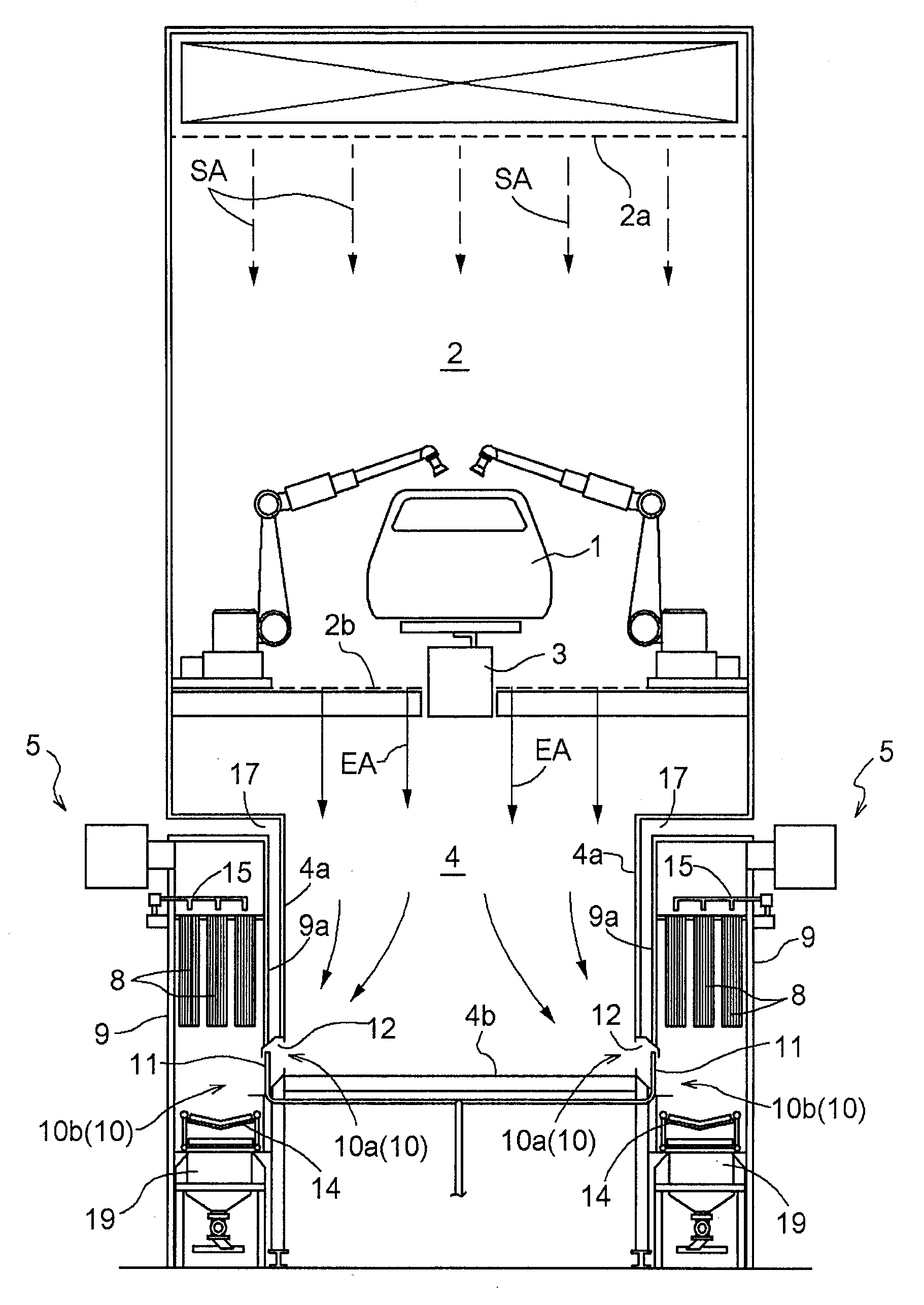
[0187] Figure 4 Shows a painting booth in which the painting booth of the first embodiment is improved. In this coating booth, the chamber width of the exhaust chamber 4 is made smaller than that of the painting chamber 2. 4, a recessed portion 17 is formed below the painting booth 2 on both lateral sides.
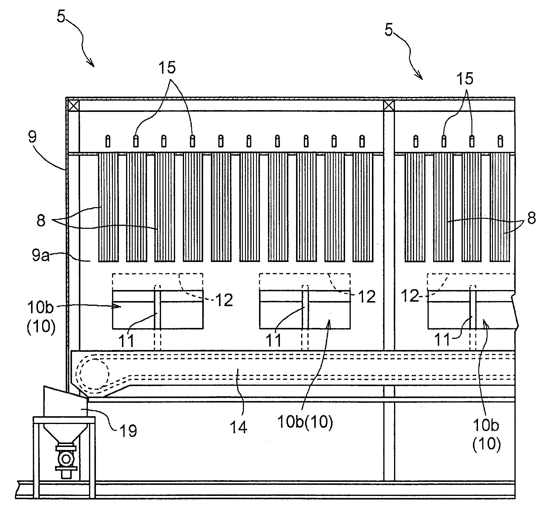
[0188] In addition, the filter devices 5 are arranged in a row in the longitudinal direction of the operating room in a state adjacent to the exhaust chamber 4 in these recessed portions 17 .
[0189] The slit-shaped inflow ports 10 of these filter devices 5 are the same as the painting operation room of the first embodiment, and are arranged along the length direction of the operation room in the same manner as the painting operation room of the first embodiment in the longitudinal direction of the operation room. They are formed in a row at the respective lower end portions of both side walls 4 a of the exhaust chamber 4 , and open into the exhaust chamber 4 at the bot...
no. 3 Embodiment approach )
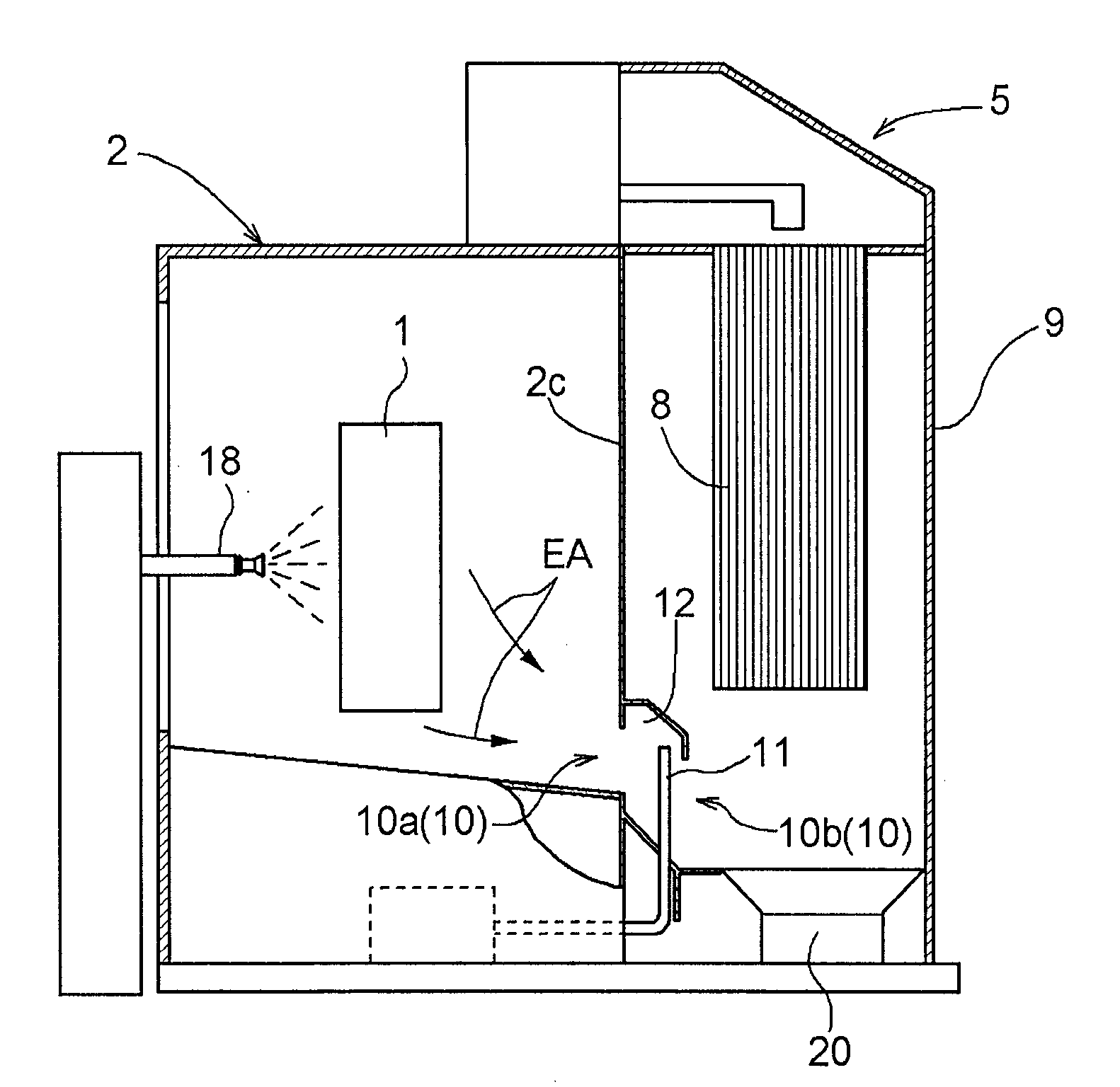
[0192] Figure 5Indicates a simple painting operation room, in which the coating gun 18 is located on the side wall of the coating room 2 for coating the object 1 to be coated. The side wall 2 c on the opposite side is used as a common form of the side wall of the device case 9 of the filter device 5 , so that the filter device 5 is adjacent to the painting booth 2 .
[0193] The inlet portion 10 of the slit-shaped filter device 5 extending in the width direction is formed at the lower end portion of the common side wall 2 c and opens to the bottom of the painting chamber 2 .
[0194] In the filter device 5, basically the same as the filter device shown in the first embodiment, the discharge air EA sucked into the device case 9 from the painting booth 2 through the slit-shaped inlet portion 10 is directed upward. The side changes direction and passes through the bag filter 8, and the paint mist in the exhaust air EA is collected by the bag filter 8.
[0195] On the inlet por...
PUM
 Abstract
Description
Claims
Application Information
 - Generate Ideas
- Intellectual Property
- Life Sciences
- Materials
- Tech Scout
- Unparalleled Data Quality
- Higher Quality Content
- 60% Fewer Hallucinations
Browse by: Latest US Patents, China's latest patents, Technical Efficacy Thesaurus, Application Domain, Technology Topic, Popular Technical Reports.
© 2025 PatSnap. All rights reserved.Legal|Privacy policy|Modern Slavery Act Transparency Statement|Sitemap|About US| Contact US: help@patsnap.com