Surge arrester with visual fault indicator

A discharger, overvoltage technology, applied in the direction of overvoltage protection resistors, varistors, etc., can solve problems such as damage indicators

Inactive Publication Date: 2011-12-07
DEHN SOHNE GMBH CO KG
View PDF2 Cites 6 Cited by
  • Summary
  • Abstract
  • Description
  • Claims
  • Application Information

AI Technical Summary

Problems solved by technology

As a result, the spring pushes the entire safety device housing into a...

Method used


Image

  • Surge arrester with visual fault indicator
  • Surge arrester with visual fault indicator
  • Surge arrester with visual fault indicator

Examples


Embodiment Construction

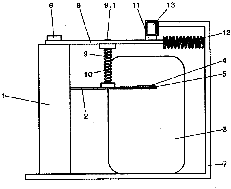
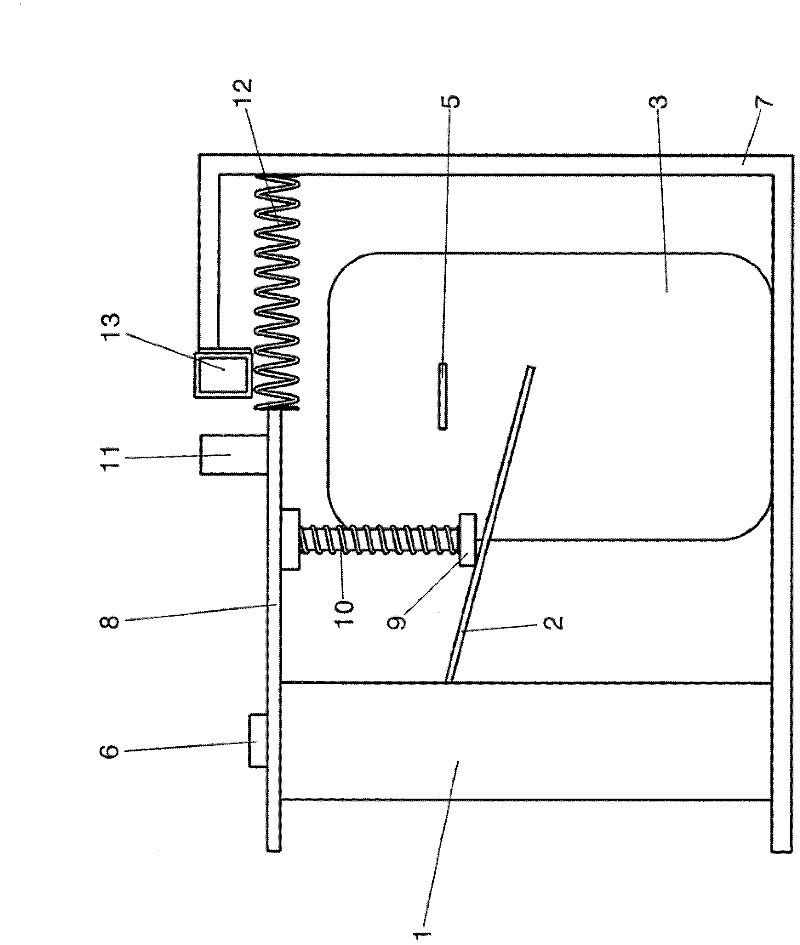
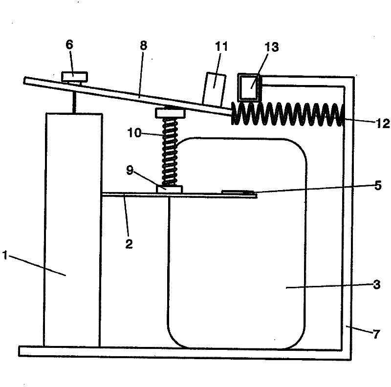
[0034] First with the aid of a simplified way to show functional structure components Figures 1 to 3 To explain the basic principle of the program of the present invention.

[0035] according to Figures 1 to 3 , starting from a thermal disconnection device in the form of a safety device 1 . The safety device 1 is connected to a discharge element, in particular a varistor 3 , via a separating tongue 2 . The connection 4 of the varistor 3 forms together with one end of the disconnecting tongue a soldered-on thermal disconnection point 5 .

[0036] Inside the safety device there are signal lines (not shown), which are connected to movable pins 6 at the upper end. When the signal wire is melted, pin 6 can be in Figures 1 to 3Medium upward movement. In a defined state of the safety device 1 the movement of the pin 6 is blocked.

[0037] The above-mentioned components are located in the housing 7, which is in the Figures 1 to 3 are only briefly shown.

[0038] Furthermore, a...


PUM


Abstract

The invention relates to a surge arrester which, in a housing (7), has at least one arrester element (3), a solder-fixed thermal disconnection point (5), which is connected to the arrester element, and a damage indicating device (11) for displaying the fault state, wherein the damage indicating device also queries the state of a thermal disconnection device, in particular a fuse, and presents the possible fault states of the arrester element and of the disconnection device mechanically in an OR combination in a suitable way. Furthermore the thermal disconnection device comprises a movable component, which is fixed by an indicator wire and is released after the melting or destruction of said wire. According to the invention, a guide part (9) for a compression spring (10) is provided on or in the housing, wherein a first spring end acts on the thermal disconnection point directly or indirectly by way of a disconnection plunger or disconnection cylinder, and a second end of the compression spring, opposite of the first end, acts on a slide (8) directly or indirectly by way of a guide ring. Furthermore, the slide is subjected to a force on a first side in the displacement direction directly by a further spring (12) or indirectly by the damage indicating device. The second side of the slide, opposite of the first side, is operatively connected to the movable component of the thermal disconnection device in such a way that it follows the release movement of the movable pin under the action of force from the compression spring. The second side of the slide is designed in such a way that a longitudinal slide movement is able to take place as a result of the force of the further spring with the thermal disconnection point triggered and the component of the thermal disconnection device fixed and also with an unchanged position between the slide and guide part and, furthermore, an ascending movement relative to the guide part is able to take place, with a subsequent longitudinal slide movement, with the indicator wire released, together with the movable component of the thermal disconnection device. The second end of the pressure spring or at least part of the guide ring engages in a cutout or depression in the slide in order to lock the latter and the damage indicating device in the proper state of the arrester.

Description

technical field [0001] The invention relates to a surge arrester according to the preamble of claim 1, which has in the housing at least one discharge element, in particular a varistor, a soldered-on thermal disconnection point connected to the discharge element and a display Damage indicator for fault states, which additionally queries the state of the thermal disconnection device, in particular the safety device, and mechanically ORs possible fault states of the discharge element and the disconnection device in a suitable visual manner In addition, the thermal disconnection device has a movable part which is fixed by the signal line and which is released after the signal line has melted or been destroyed. Background technique [0002] For example, DE 77 19 678 U1 discloses a surge arrester with at least one voltage-dependent resistance and a thermal cut-off device, which includes a fuse link and a thermal trigger device with a eutectic eutectic alloy, with the fuse link or...

Claims


Application Information

Patent Timeline
IPC IPC(8): H01C7/12
CPCH01C7/12
Inventor R·道姆
Owner DEHN SOHNE GMBH CO KG
Why Eureka
Try Eureka