A device to reduce buffer force

A cushioning force and cushioning layer technology, applied in transportation and packaging, railway car body parts, cargo support/fastening parts, etc., can solve problems such as uneven quality of grass products, lack of grass resources, and insufficient length of straw

Inactive Publication Date: 2011-12-14
BEIJING RUI LI HENG YI LOGISTICS TECH PLC
View PDF5 Cites 1 Cited by
  • Summary
  • Abstract
  • Description
  • Claims
  • Application Information

AI Technical Summary

Problems solved by technology

Due to the lack of grass resources, the length of straw is not standard enough, resulting in uneven quality of grass products, which brings many hidden dangers to the safety of coil steel transportation

Method used


Image

  • A device to reduce buffer force
  • A device to reduce buffer force
  • A device to reduce buffer force

Examples


Embodiment 1

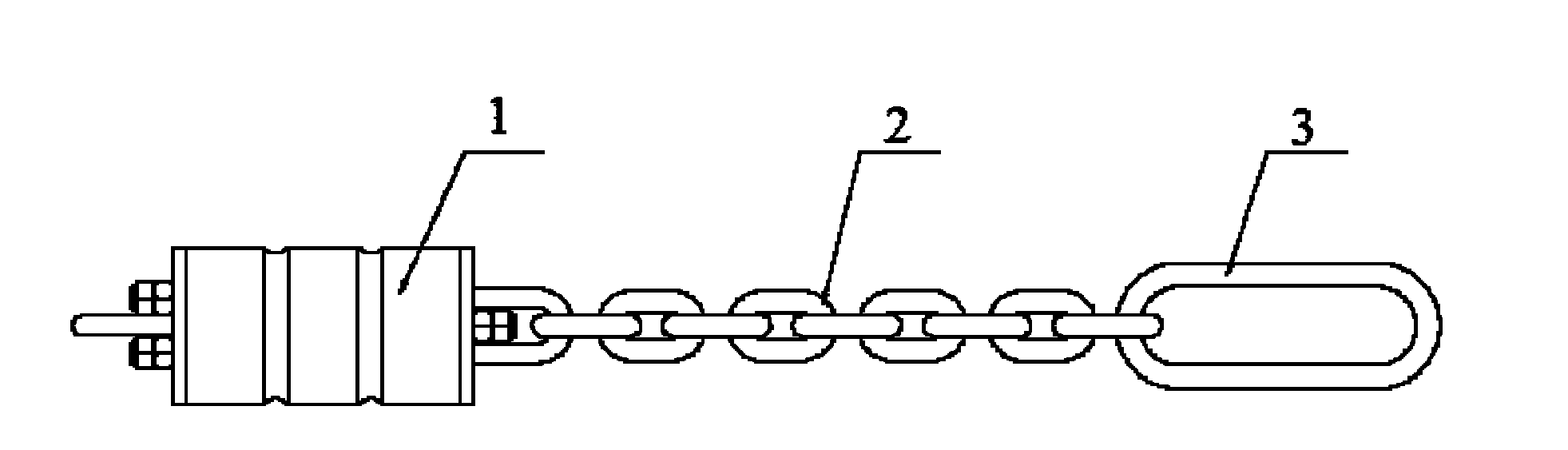
[0025] figure 1 It shows a schematic structural view of the device for reducing buffer force in this embodiment, which includes a buffer unit and a connecting unit, and the structural schematic view of the buffer unit is as follows Figure 4 shown. The buffer unit includes a buffer layer 7 and connecting rods passing through the buffer layer. There are at least two connecting rods, which respectively pass through the buffer layer 7 oppositely; this embodiment uses two connecting rods as an example to introduce the structure of the buffer unit.

[0026] Buffer layer 7 comprises at least one layer, and when buffer layer 7 is more than one layer, is separated by separator 8 between several buffer layers 7, and baffle plate 9 is set respectively at the two ends of buffer unit, buffer layer 7, The partition plate 8 and the baffle plate 9 are combined together to form a stacking mechanism, on which four through holes are provided in a cross shape in the axial direction, and the fir...

Embodiment 2

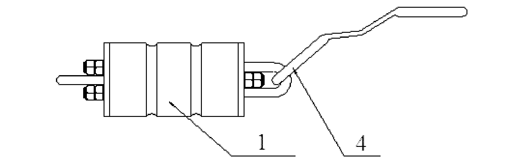
[0031] figure 2 A schematic structural view of the device for reducing buffer force of this embodiment is shown. The structure of the device for reducing buffer force in this embodiment is similar to that of the device for reducing buffer force in Embodiment 1, except that the structure of the connecting unit is different.

[0032] The connection unit of this embodiment includes a door ring 4, and the structure of the door ring 4 is: the lower part is a semi-circular ring, which is used to hang on the T-shaped iron of the gondola; Between the opening of the door; the upper part is an inwardly inclined semi-circular ring, which is exposed in the open car and can be used to bundle and reinforce the goods in the open car.

[0033] The device for reducing the buffer force of the present embodiment is suitable for gondola carriages.

Embodiment 3

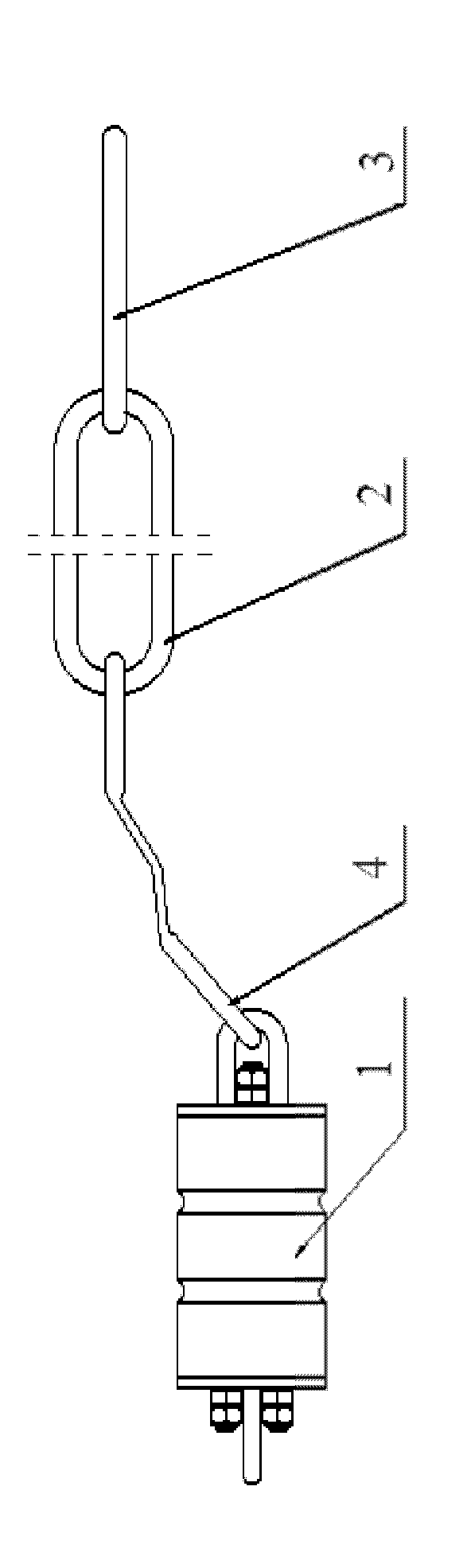
[0035] image 3 A schematic structural view of the device for reducing buffer force of this embodiment is shown. The device for reducing buffer force in this embodiment is similar in structure to the device for reducing buffer force in Embodiment 1, except that the structure of the connecting unit is different.

[0036] The connection unit in this embodiment includes a door ring 4 , a connecting chain 2 and a hanging ring 3 , the door ring 4 is connected to the buffer unit, and the connecting chain 2 is connected between the door ring 4 and the hanging ring 3 .

[0037] The structure of the door ring 4 of this embodiment is the same as that of the door ring in Embodiment 2. The length of the connecting chain 2 is determined according to the size of the means of transport and the arrangement height of the goods to be transported.

[0038] It can be seen from the above embodiments that the device for reducing the buffer force provided by the embodiments of the present inventio...


PUM


Abstract

The invention relates to the field of cargo transportation, and discloses a device for reducing buffer force, which includes a buffer unit and a connection unit connected thereto, the buffer unit includes a buffer layer and a connecting rod passing through the buffer layer, and the connecting rod has at least Two of them pass through the buffer layer oppositely; one end of the connecting rod is arranged in a ring shape, and the other end is stuck outside the buffer layer. When the buffer force reducing device of the present invention acts on the transported goods, it can absorb and slow down the longitudinal inertial force received by the goods to be reinforced, save the use of reinforcement materials, reduce operating time, reduce reinforcement costs, and improve reinforcement performance, thereby ensuring transportation safety ; And the device for reducing the buffering force cooperates with strip-shaped straw pads and wire rope fasteners, which is suitable for bundling and reinforcement of open and flat vehicles, and the transportation safety performance is greatly improved.

Description

technical field [0001] The invention relates to the field of cargo transportation, in particular to a device for reducing buffer force. Background technique [0002] In the process of railway cargo transportation, the fixing of goods is particularly important, because it is closely related to transportation safety. Taking coil steel transportation as an example, the existing reinforcement scheme for horizontally loaded coil steel uses concave straw pads or straw cover for reinforcement. Due to the lack of grass resources, the length of straw is not standard enough, resulting in uneven quality of grass products, which brings many hidden dangers to the safety of coil steel transportation. Contents of the invention [0003] (1) Technical problems to be solved [0004] The technical problem to be solved by the present invention is how to fix the goods transported by rail, provide buffer force for the transported goods, and improve the safety of transportation. [0005] (2) ...

Claims


Application Information

Patent Timeline
Patent Type & Authority Applications(China)
IPC IPC(8): B61D45/00
Inventor 高绪坤林雨雷杨军李祝
Owner BEIJING RUI LI HENG YI LOGISTICS TECH PLC
Why Eureka
Try Eureka