Check patentability & draft patents in minutes with Patsnap Eureka AI!

Screw drive

A technology of driving device and screw rod, which is applied in the direction of transmission device, hoisting device, portable lifting device, etc., can solve the problems of unstable movement of the screw rod, insufficient accuracy of the manufacturing accuracy of the worm gear and the position of the bearing at the threaded connection, etc. Simple, stable motion, easy to use effect

Inactive Publication Date: 2011-12-14
JIANGSU VICTORY MACHINERY
View PDF3 Cites 7 Cited by
  • Summary
  • Abstract
  • Description
  • Claims
  • Application Information

AI Technical Summary

Problems solved by technology

The disadvantage of the above-mentioned screw driving device is that there is inevitably a certain gap at the threaded connection between the worm and the screw due to insufficient manufacturing precision and the positional accuracy of the worm wheel and the bearing, which will cause the screw to move unstable during operation.

Method used


Image

  • Screw drive
  • Screw drive

Examples


Embodiment Construction

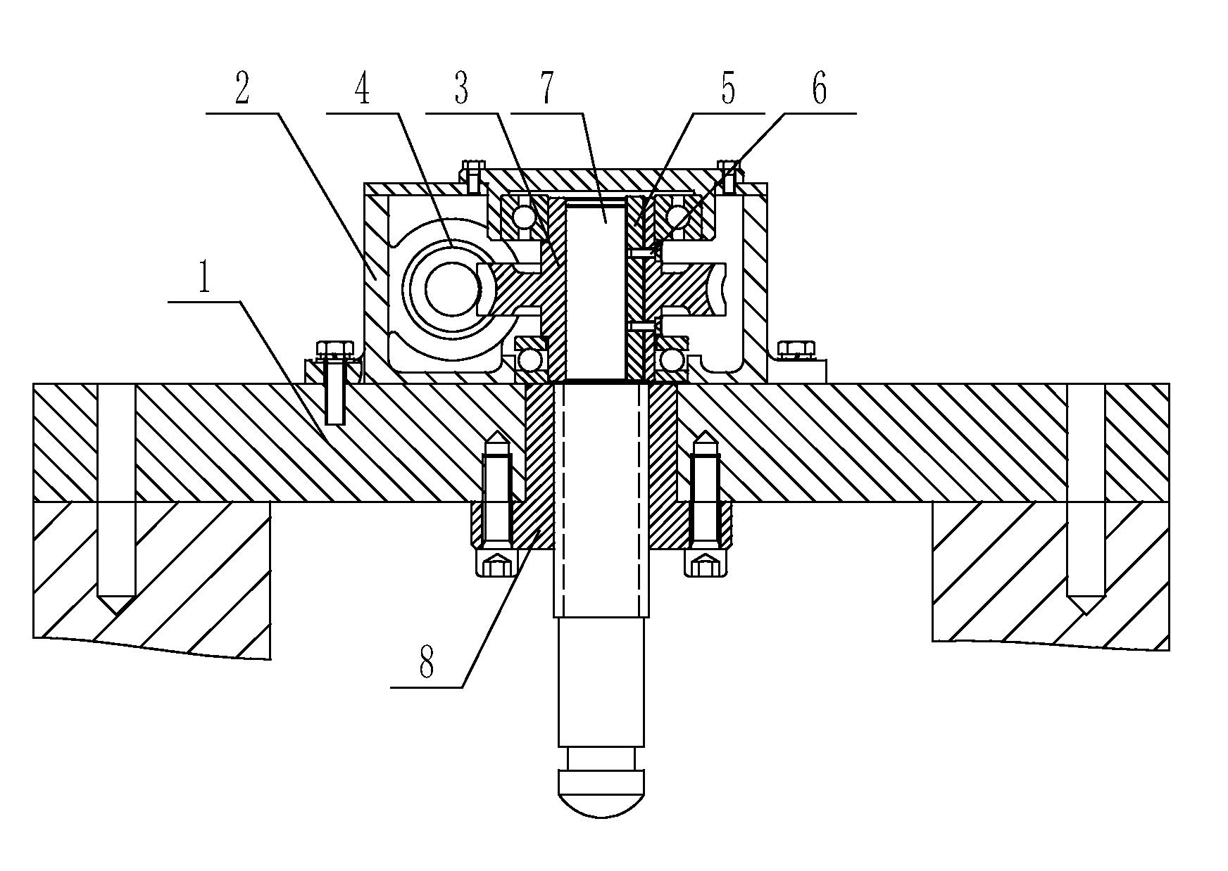
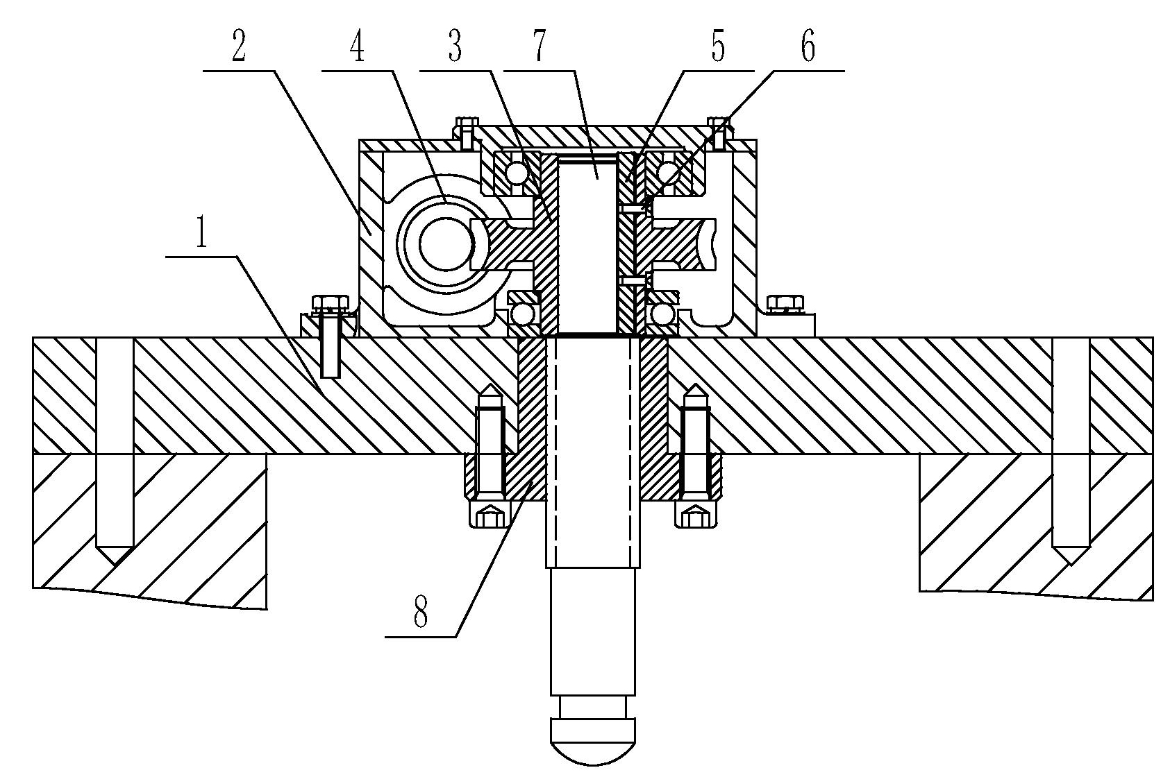
[0009] The screw driving device of the present invention will be further described in detail through specific embodiments below.

[0010] Such as figure 1 As shown, the screw driving device includes a frame 1, and a reduction box 2 is arranged on the frame 1, and a worm wheel 3 and a worm 4 that cooperate with each other are arranged inside the reduction box 2, and the inner wall of the worm wheel 3 is smooth and is provided with The key 5, the key 5 is fixed inside the worm wheel 3 through the bolt 6, the worm wheel 3 is connected with the screw rod 7, the upper part of the screw rod 7 is set in the worm wheel 3, the outer wall of the upper part of the screw rod 7 is smooth and is provided with a key hole, and the key hole runs through the screw rod 7, the key 5 is arranged in the keyhole, the outer wall of the lower part of the screw mandrel 7 is provided with threads, the lower part of the screw mandrel 7 is covered with a shaft sleeve 8, the shaft sleeve 8 is connected wit...


PUM


Abstract

The invention relates to a screw driving device, which comprises a frame, on which a reduction box is arranged, and inside the reduction box, a worm wheel and a worm that cooperate with each other are arranged, the inner wall of the worm wheel is smooth and a key is arranged in the inner wall, and the worm wheel is connected with a wire The upper part of the screw rod is set in the worm wheel, the upper outer wall of the screw rod is smooth and is provided with a key hole, the key hole runs through the upper end of the screw rod, the key is arranged in the key hole, the lower outer wall of the screw rod is provided with threads, and the outer wall of the screw rod is provided with threads. The lower sleeve is provided with a shaft sleeve, which is connected with the screw rod through threads, and the shaft sleeve is arranged on the frame. The invention is suitable for driving the screw rod to move up and down, and can make the screw rod move stably.

Description

technical field [0001] The invention relates to a screw drive device for driving the screw to rotate. Background technique [0002] The currently used screw driving device has a structure including a frame, on which a reduction box is arranged, and a worm gear and a worm that cooperate with each other are arranged inside the reduction box, the worm wheel is provided with an internal thread, the screw is arranged in the worm wheel, and the screw The thread of the thread meshes with the internal thread. Its working principle is: the worm rotates under the drive of the motor, the rotation of the worm drives the worm wheel to rotate, and the rotation of the worm wheel makes the screw move up and down through the thread inside the worm wheel. The disadvantage of the above-mentioned screw driving device is that there is inevitably a certain gap between the threaded connection between the worm and the screw due to insufficient manufacturing precision and the matching accuracy of t...

Claims


Application Information

Patent Timeline
Patent Type & Authority Applications(China)
IPC IPC(8): F16H37/02F16H57/02F16H55/22F16H25/24F16B3/00
Inventor 朱先福陆新海李斌周丽芳张正俊顾晓熙仇庆武赵启红吴建华
Owner JIANGSU VICTORY MACHINERY
Features
  • R&D
  • Intellectual Property
  • Life Sciences
  • Materials
  • Tech Scout
  • Unparalleled Data Quality
  • Higher Quality Content
  • 60% Fewer Hallucinations
Learn More