Check patentability & draft patents in minutes with Patsnap Eureka AI!

Density triangular driving mechanism for computer flat knitting machine

A technology of density triangle and drive mechanism, applied in the directions of knitting, weft knitting, textiles and papermaking, etc., can solve problems such as motion deviation, and achieve the effect of eliminating motion deviation

Inactive Publication Date: 2008-07-09
JIANGSU JINLONG TECHNOLOGY CO LTD
View PDF0 Cites 3 Cited by
  • Summary
  • Abstract
  • Description
  • Claims
  • Application Information

AI Technical Summary

Problems solved by technology

[0004] The shortcoming of the above-mentioned mechanism is: no matter from the perspective of the processing technology of the parts or the assembly angle of the parts, it is impossible to make the first roller 31 and the groove of the roller groove 22 The wall is maintained to a satisfactory degree of contact, that is to say, during the movement, there is a movement gap between the first roller 31 and the roller groove 22, which is specifically shown as: the position of the first roller 31 in the roller groove 22 exists Two kinds of uncertain sticking positions, that is, it is possible to stick to the upper groove wall of the roller groove 22, and it is also possible to stick to the lower groove wall of the roller groove 22, and the existence of the gap will cause the density triangle 6 to produce motion deviation, the gap The magnitude of the deviation is equal to the movement deviation of the density triangle 6, and the known deviation is 0.04-0.05mm. Although the deviation seems insignificant for a row of fabric, it is enough to accumulate to restrict the improvement of fabric grade.

Method used


Image

  • Density triangular driving mechanism for computer flat knitting machine
  • Density triangular driving mechanism for computer flat knitting machine

Examples


Embodiment Construction

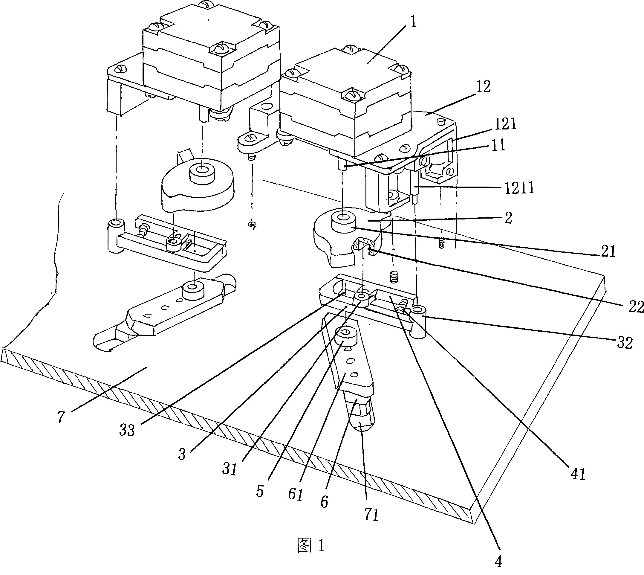
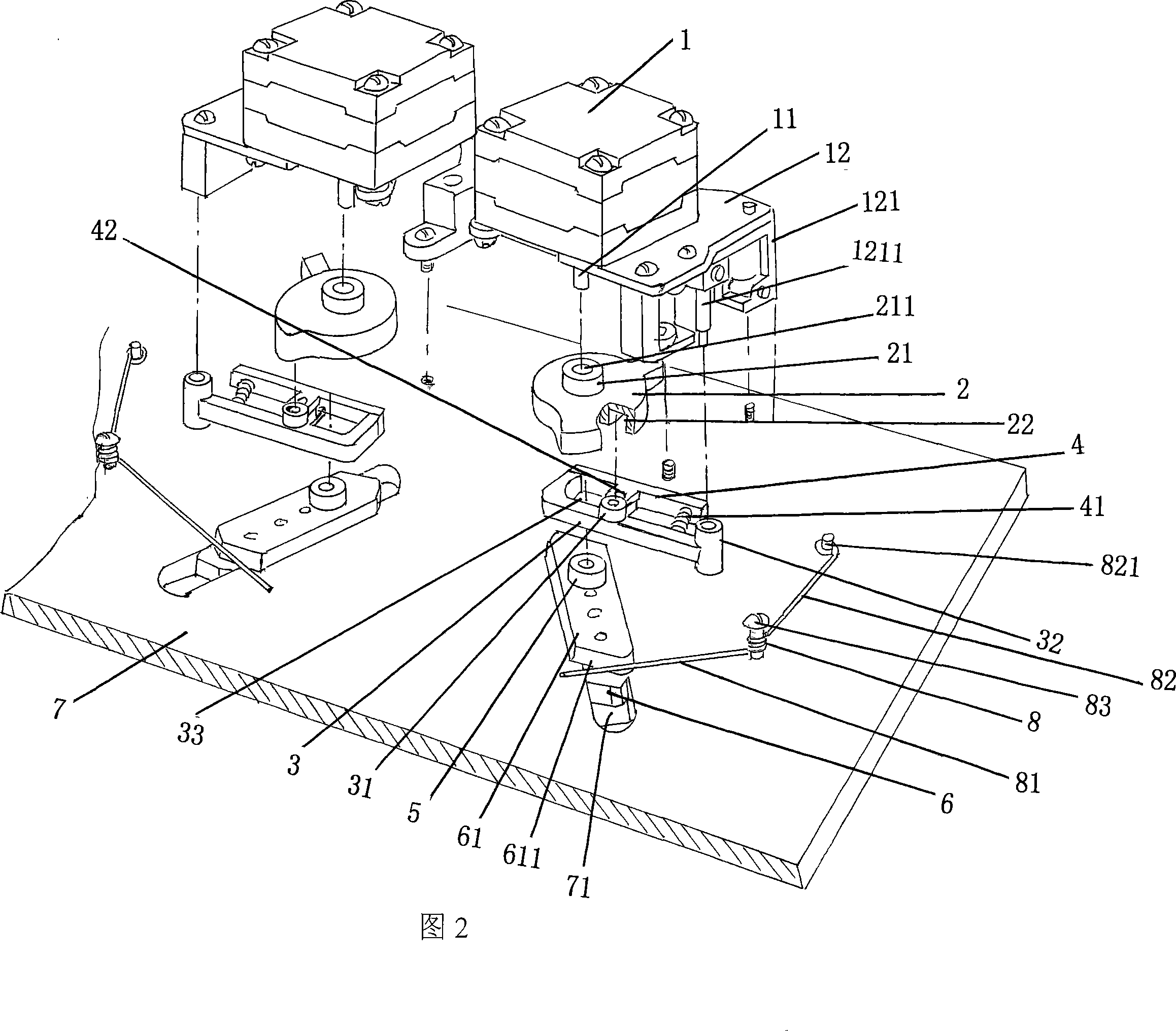
[0013] Please refer to Fig. 2, the applicant has mentioned earlier that the machine head of the weaving mechanism has a pair of triangular base plates 7, and a pair of density cams 6 are arranged on each triangular base plate 7, and each density cam 6 is equipped with a set of density triangular drive mechanisms , under the action of this mechanism, the density triangle 6 is moved up and down on the preset density triangle adjustment groove 71 on the triangle bottom plate 7 under the guidance of the density triangle guide block 61 . Based on an example by analogy, the following only describes the adjustment mechanism of one of the density triangles 6 .

[0014] The motor 1 of the density triangular drive mechanism of the computerized flat knitting machine recommended by the present invention is a motor with forward and reverse functions, which is placed on the motor base 12, and the motor base 12 is fixed to the triangular bottom plate 7 with screws through the bracket 121 A r...


PUM


Abstract

The invention relates to a density triangle drive mechanism of a flat knitting machine of computerized knitting, which belongs to the technical field of knitting machines. The invention comprises a motor, a cam, a clipping arm, a spring clipping plate and a second rolling wheel, the motor is arranged on a motor base, the motor base is fixed on a triangle bottom board, a motor shaft of the motor is drivingly interlocked with the cam, a rolling wheel groove is formed on one side of the cam, the upper surface of the clipping arm is provided with a first rolling wheel, and one end of the clipping arm is pivoted on a supporting stand, and a rolling wheel cavity is formed on the other end, a near middle part of the spring clipping plate is hinged with the clipping arm, and one end is interlocked with the clipping arm, and the other end contacts with the corresponded end of the clipping arm, a second rolling wheel is arranged on a density triangle guide block which is arranged on the rear surface of a density triangle and is embraced in the rolling wheel cavity. The invention is characterized in that the invention also comprises a blocking spring which is provided with a first spring arm and a second spring arm, the middle part of the blocking spring is located on the triangle bottom board through any locate mode of a direct locate mode and an indirect locate mode, and the first spring arm contacts with the density triangle guide block, and a second spring arm is fixed on the triangle bottom board. The invention has the advantages that motion deviation of the density can be eliminated.

Description

technical field [0001] The invention belongs to the technical field of knitting machinery, and in particular relates to a density triangle driving mechanism of a computerized flat knitting machine. Background technique [0002] As the technical personnel in the field know well, a pair of triangular bottom plates (the industry is customarily called the front and rear triangular bottom plates) are fixedly installed on the head of the knitting mechanism of the computerized flat knitting machine, and each triangular bottom plate is movably provided with a For density triangles, the movement of each density triangle is realized by the work of the corresponding density triangle drive mechanism. When the knitting mechanism of the computerized flat knitting machine is in the state of knitting with yarn, the head reciprocates once every time it is left and right, and the density triangle moves up and down correspondingly. [0003] The specific structure of the density triangular dri...

Claims


Application Information

Patent Timeline
IPC IPC(8): D04B15/36D04B15/96
Inventor 金永良海港
Owner JIANGSU JINLONG TECHNOLOGY CO LTD
Features
  • R&D
  • Intellectual Property
  • Life Sciences
  • Materials
  • Tech Scout
  • Unparalleled Data Quality
  • Higher Quality Content
  • 60% Fewer Hallucinations
Learn More