a pneumatic valve

A technology of air pressure valve and tubular body, which is applied in the field of valve devices and air pressure valves, and can solve problems such as easy corrosion, loss of function of pressure relief valve, loss of spring 41, etc.

Inactive Publication Date: 2011-12-14
张秋艳
View PDF0 Cites 4 Cited by
  • Summary
  • Abstract
  • Description
  • Claims
  • Application Information

AI Technical Summary

Problems solved by technology

[0003] However, since the spring 41 is made of metal, long-term use is prone to corrosion, so that the spring 41 loses its original function of resisting the ball 3, and then the entire pressure relief valve loses its function.

Method used


Image

  • a pneumatic valve
  • a pneumatic valve
  • a pneumatic valve

Examples


Embodiment Construction

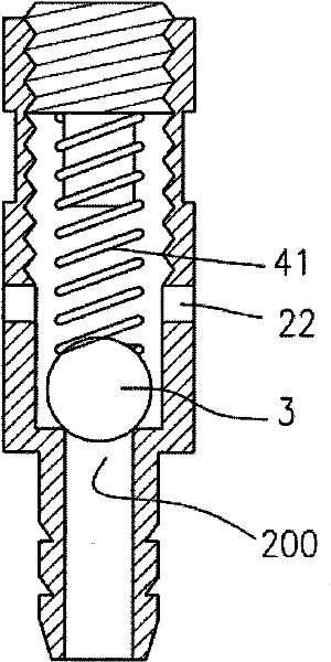
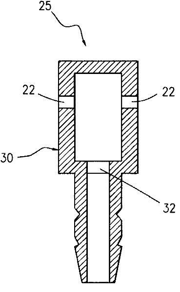
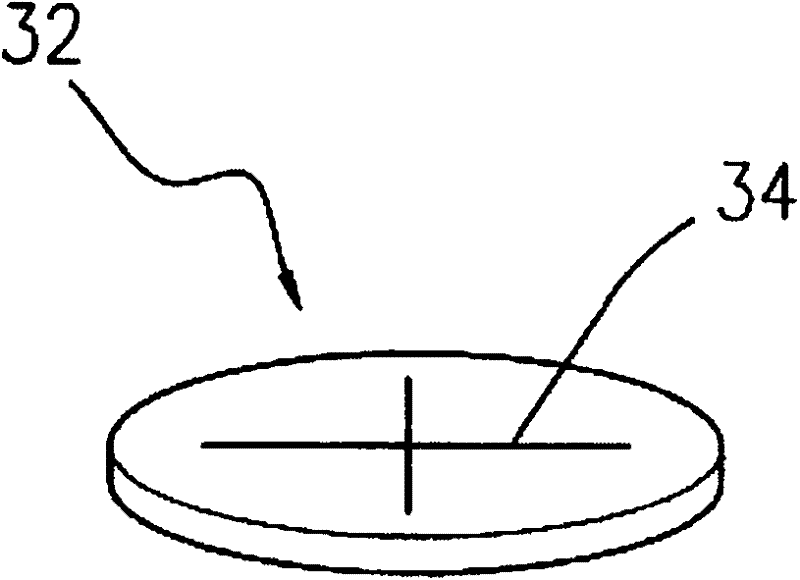
[0013] as attached figure 2 , 3 Shown is a pneumatic valve 25 of the present invention, which is mainly composed of a tubular body 30, an elastic plug body 32, and a pressure relief slit 34 pierced through the elastic plug body 32, and the shape is trident, cross, and rice. or other types of slits. The edge of the elastic plug body 32 is completely against the wall of the tubular body, and the selected material can be silica gel or latex material. Therefore, although the elastic plug body 32 has been penetrated, due to its own elasticity, the When no external force is applied or the active force is not large enough, the gas in the tubular body 30 still cannot flow to the gas release part 22 through the pressure relief slit of the elastic plug body 32 (as attached image 3 shown).

[0014] When the gas flows to the elastic plug body 32 through the tubular body 30, when the impact pressure brought by the gas is greater than the resistance of the slit 34 of the elastic plug b...


PUM


Abstract

The invention discloses an air pressure valve, which comprises: a tubular body; an elastic plug body made of elastic material, the edge of the elastic plug body is completely against the pipe wall of the tubular body, and the elastic plug body further includes a The slits are perforated on the elastic plug body. When the gas flows to the elastic plug body through the tubular body, when the impact pressure is greater than the resistance of the slit of the elastic plug body, holes can be formed along the intersection of the slits, so that the fluid can pass through the elastic plug body to achieve pressure relief the goal of.

Description

technical field [0001] The invention relates to a valve device, in particular to a pneumatic valve, and belongs to the technical field of engineering components. Background technique [0002] figure 1 It is a structural schematic diagram of a pneumatic valve in the prior art. Its working principle is as follows: if the high-pressure gas enters through the air inlet, the impact force brought by it will push the ball 3 . If the impact force is greater than the resisting force of the spring 41, the ball 3 that previously blocked the air intake portion 200 will no longer continue to block, and the high-pressure gas will flow to the vent portion 22, so that the high-pressure gas is discharged. [0003] However, since the spring 41 is made of metal, long-term use is prone to corrosion, so that the spring 41 loses its original function of resisting the ball 3, and then the entire pressure relief valve loses its function. [0004] In order to avoid the above-mentioned technical p...

Claims


Application Information

Patent Timeline
Patent Type & Authority Applications(China)
IPC IPC(8): F16K17/18
Inventor 张秋艳
Owner 张秋艳
Why Eureka
Try Eureka