A power distribution method, device and system

An allocating method and power technology, applied in the field of communication, can solve problems such as low utilization rate of total power resources

Inactive Publication Date: 2014-10-29
深圳市恒程汇文化科技有限公司
View PDF3 Cites 0 Cited by
  • Summary
  • Abstract
  • Description
  • Claims
  • Application Information

AI Technical Summary

Problems solved by technology

[0004] Embodiments of the present invention provide a power allocation method, device, and system to solve the problem of low utilization of total power resources allocated to multiple cells in the prior art, thereby increasing the downlink rate of the cells

Method used


Image

  • A power distribution method, device and system
  • A power distribution method, device and system
  • A power distribution method, device and system

Examples


Embodiment 1

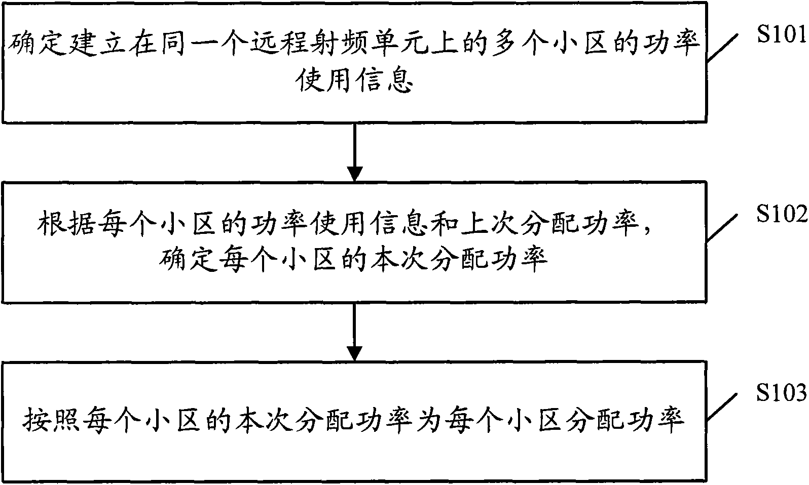
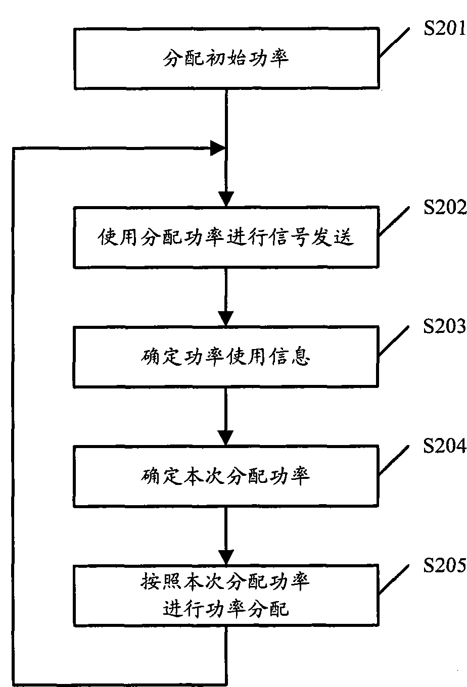
[0028] Embodiment 1 of the present invention provides a power allocation method, such as figure 2 shown, including:

[0029] Step S201, divide multiple cells established on a remote radio frequency unit into a cell group, these multiple cells can be all the cells established on the remote radio frequency unit, or select appropriate part of the cells according to the needs of the implementation of the scheme .

[0030] The initial power is allocated to each cell in the divided cell group, and the specific initial power allocation scheme may adopt the existing technology, which will not be described in detail here.

[0031] Step S202, after allocating power to each cell, each cell transmits downlink signals according to its allocated power.

[0032] Step S203, when the power allocation cycle arrives, determine the power usage information of each cell; the power usage information of the cell represents the power usage of the cell after the last power allocation, which can be s...

Embodiment 2

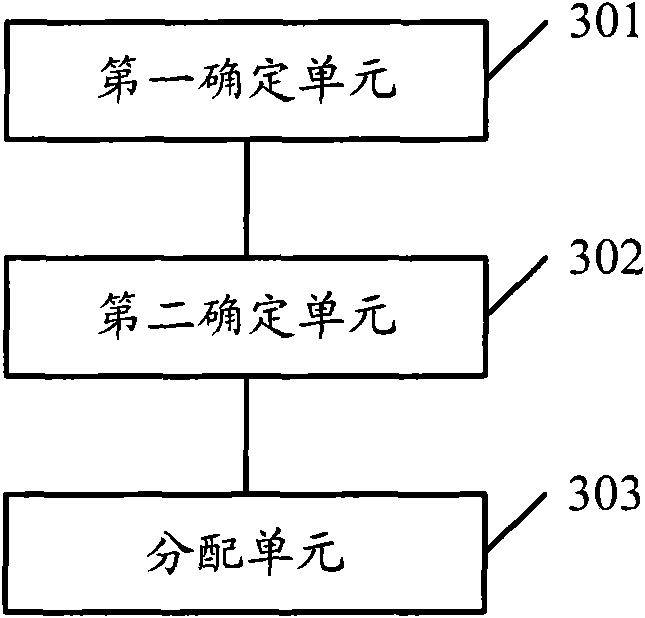
[0052] Based on the same inventive concept, according to the power sharing method provided in the first embodiment of the present invention, the second embodiment of the present invention also provides a power sharing device correspondingly, the structural diagram of which is as follows image 3 shown, including:

[0053] The first determining unit 301 is configured to determine the power usage information of multiple cells established on a remote radio frequency unit; the power usage information represents the power usage of the cells after the last power allocation;

[0054] The second determination unit 302 is configured to determine the current allocation power of each cell according to the determined power usage information and the last allocation power of each cell; wherein, the sum value of the last allocation power of each cell and the current allocation The sum of power is equal;

[0055] The allocation unit 303 is configured to allocate power to each cell according ...

Embodiment 3

[0062] Based on the same inventive concept, according to the power sharing method provided by the first embodiment of the present invention, correspondingly, the third embodiment of the present invention also provides a power sharing system, the schematic diagram of which is as follows Figure 4 As shown, it includes: power access PA management unit 401 and PA general scheduler 402, wherein:

[0063] The PA management unit 401 is used to determine the power usage information of multiple cells managed by itself established on a remote radio frequency unit; and report the determined power usage information of each cell to the PA general scheduler; the power usage information represents The power usage of the cell after the secondary power allocation; and receive the current allocated power of each cell sent by the PA master scheduler; and allocate power to each cell according to the received current allocated power of each cell;

[0064] The PA general scheduler 402 is configure...


PUM


Abstract

The invention discloses a power allocation method, device and system, comprising: determining the power usage information of multiple cells established on the same remote radio frequency unit; the power usage information of the cells represents the power usage of the cell after the last power allocation and according to the determined power usage information of each cell and the last allocated power, determine the current allocated power of each cell; wherein, the sum of the last allocated power of each cell is equal to the sum of this allocated power ; and allocate power to each cell according to the determined current allocated power of each cell. By adopting the method, device and system provided by the present invention, the problem of low utilization rate of total power resources allocated to multiple cells in the prior art is solved, and the downlink rate of the cells is further improved.

Description

technical field [0001] The present invention relates to the technical field of communications, and in particular to a power distribution method, device and system. Background technique [0002] At present, a wireless enhancement technology HSDPA (High Speed ​​Downlink Packet Access, High Speed ​​Downlink Packet Access) technology is introduced into the WCDMA system R5 protocol in the field of 3G technology. By introducing the HSDPA technology, the downlink rate of the cell is continuously improved. At the same time, for the terminal, the improvement of the downlink rate requires better channel conditions, that is, the downlink transmission power of the base station must be large enough to ensure the normal reception of the downlink signal by the terminal. [0003] In the current power allocation technology, for the multiple cells included in the base station, the maximum downlink transmission power allocated to each cell is unchanged, so it often happens that one cell has in...

Claims


Application Information

Patent Timeline
Patent Type & Authority Patents(China)
IPC IPC(8): H04W52/22H04W52/34
Inventor 刘志斌戚丽丽李瑞峰
Owner 深圳市恒程汇文化科技有限公司
Why Eureka
Try Eureka