

Solar profile automatic production line
An automatic production line and solar profile technology, applied in the direction of connecting components, mechanical equipment, etc., can solve the problems of excessive manual processes, low production efficiency, high production costs, etc., to reduce production costs, reduce labor costs, installation and use The effect of convenient work
- Summary
- Abstract
- Description
- Claims
- Application Information
AI Technical Summary
Problems solved by technology
Method used
Image

Examples
Embodiment Construction
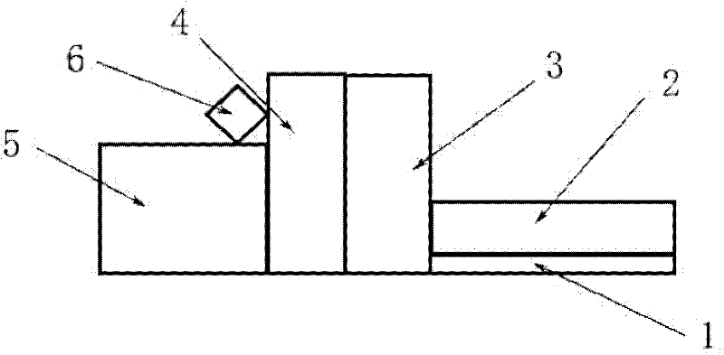
[0032] Such as figure 1 As shown, the solar profile automatic production line of the present invention is composed of a feeding support part 1, a feeding and conveying part 2, a tape pasting part 3, a punching part 4, a bending part 5 and a control cabinet 6.
[0033] Such as figure 1 The shown feeding support part 1, tape sticking part 3, punching part 4, and bending part 5 are connected in sequence, the feeding support part 1 and the feeding conveying part 2 are connected together side by side, and the control cabinet 6 is placed in the punching part 4 and the bending part 5, and connect with each part of the whole production line through lines.
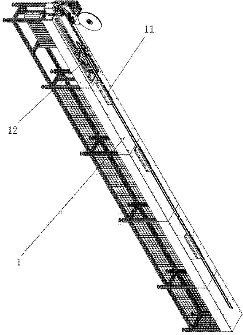
[0034] Such as figure 2 , Figure 8 As shown, the feeding support part 1 is composed of a support positioning structure 11 and a traveling device 12. The support positioning structure 11 completes the positioning of the profile, and the traveling device 12 adjusts the speed of the profile according to the 6 commands of the cont...
PUM
 Abstract
Description
Claims
Application Information