ride-on vehicle

A riding-type vehicle and frame technology, which is applied to motorcycles, bicycles, motor vehicles, etc., can solve the problems of deterioration of rider comfort and achieve the effect of enhancing ventilation performance

Active Publication Date: 2011-12-21
YAMAHA MOTOR CO LTD
View PDF8 Cites 0 Cited by
  • Summary
  • Abstract
  • Description
  • Claims
  • Application Information

AI Technical Summary

Problems solved by technology

Therefore, warm air may worsen rider comfort

Method used


Image

  • ride-on vehicle
  • ride-on vehicle
  • ride-on vehicle

Examples


Embodiment Construction

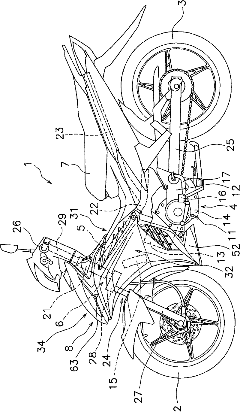
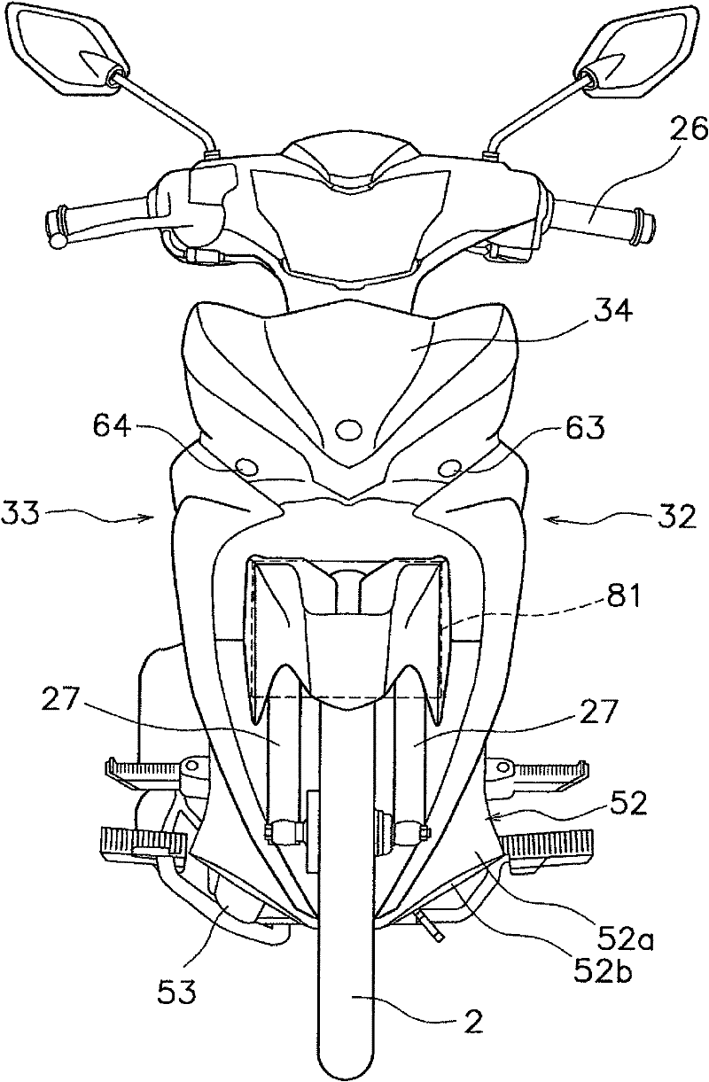
[0050] Hereinafter, exemplary embodiments of the present invention will be described with reference to the accompanying drawings. figure 1 is a side view of the saddle type vehicle 1 according to the exemplary embodiment of the present invention. figure 2 It is a front view of the saddle type vehicle 1 . The saddle type vehicle 1 is a so-called moped. In the saddle type vehicle 1 , a portion interposed between the seat 7 to be described and the manipulation portion 6 to be described is formed in a downwardly concave shape in the longitudinal direction (rear-rear direction) of the vehicle body. It should be noted that in the following description, unless explicitly stated otherwise, directional terms such as "front", "rear", "right", "left" and related terms refer to the direction from which the ride-on vehicle 1 is seated. The direction seen by the rider on seat 7. In addition, the term "lateral" and related terms refer to a direction away from the center of the vehicle bo...


PUM


Abstract

It is an object of the present invention to inhibit rider's comfortableness from being deteriorated by the warmed air flowing out of a vehicle body cover in a saddle-ride type vehicle. A vehicle body cover (8) of a saddle-ride type vehicle includes plural slanted surfaces (41a-41c) on a top surface section (31) thereof. Each of the slanted surfaces (41a and 41b) is slanted for positioning the front portion thereof higher than the rear portion thereof. The slanted surfaces (41a and 41b) are disposed at a predetermined interval in a longitudinal direction of the vehicle body. The slanted surfaces (41a and 41b) form an air path (44a) therebetween. The air path (44a) communicates with the inner space enclosed by the vehicle body cover (8). The top surface section (31) includes a first blade (42a) extended rearwards over the slanted surface (41a).

Description

technical field [0001] The present invention relates to a riding type vehicle. Background technique [0002] In some known saddle-type vehicles such as the motorcycle described in Japanese Patent Laid-Open No. JP-A-2004-291700, a body cover is arranged between the handlebar and the seat. The car body cover is located in front of the vehicle seat, while the engine is arranged under the car body cover. The vehicle body cover includes an opening. A plurality of fins are attached to the opening. The fins protrude from the vehicle body cover while being arranged perpendicularly to the vehicle body cover. [0003] In motorcycles of the above-mentioned type, the engine is arranged under the body cover. When the motorcycle is running or stopped, the air warmed by the heat of the engine flows out from the opening of the body cover. The warm air blown out from the opening flows upward and backward while being guided by the fins. Simply put, the warm air blown from the opening te...

Claims


Application Information

Patent Timeline
Patent Type & Authority Applications(China)
IPC IPC(8): B62J17/00
CPCB62J17/02B62J25/00B62J33/00B62M7/04B62K11/04B62K2202/00B62J17/10
Inventor 吹田善一神村薰
Owner YAMAHA MOTOR CO LTD
Why Eureka
Try Eureka