
Water flow generator

A generator and flowing water technology, applied in hydroelectric power generation, engine components, machines/engines, etc., can solve problems such as inability to realize industrialization and industrial production, failure to give full play to the advantages of flowing water potential energy, and inability to enter industrial production and application. Achieve the effect of saving space investment, easy popularization and application, and low loss

Inactive Publication Date: 2012-12-19
腾传文 +2
View PDF15 Cites 0 Cited by
  • Summary
  • Abstract
  • Description
  • Claims
  • Application Information

AI Technical Summary

Problems solved by technology

At present, the patented technology of flowing water power generation that has been researched and developed in the country is basically unable to realize industrialization and industrial production: for example: Chinese patent application number: 200820077968.4 "floating water turbine generator", Chinese utility model patent: 200420020850.2 "a flowing water power generation device" , Chinese utility model patent: 95241930.0 "flowing water power generation device", Chinese utility model patent: 200520121400.4 "floating flowing water power generation device", Chinese invention patent application number: 200710106615.2 "flowing water power station", Chinese utility model patent number 200810077968.4 "floating water wheel Generator", Chinese utility model patent: 99219281.1 "river water power generation device" and other technical patents
All have different problems and cannot enter industrial production and application
[0003] The main problems are: 1. The advantages of the potential energy of flowing water are not fully utilized, and the kinetic energy of flowing water cannot be effectively converted into electrical energy only from the transformation of mechanical motion.
2. The process is complex, relying heavily on other objective conditions, and lacking a stable, safe and reliable operation basis
For example: Chinese invention patent application number: 200710106615.2 "flowing water power station", Chinese utility model patent: 200420020850.2 "a flowing water power generation device", etc.; 3. The amount of kinetic energy collection is low, the conversion rate of flowing water potential energy is weak, and the loss of mechanical transmission is large, so it has entered the industry Insufficient conditions in the stage of transformation

Method used


Image

  • Water flow generator
  • Water flow generator
  • Water flow generator

Examples


Embodiment 1

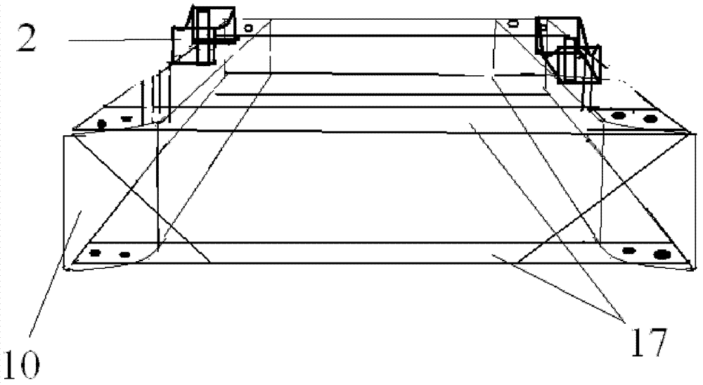
[0029] Embodiment 1: The floating water tank 10 is welded with a marine steel plate, and the inner side of the front end of the floating water tank 10 is made into an oblique angle, extending from the outside to the inside to one-fifth of the box body. The inside of the floating water tank 10 is a reinforced skeleton structure, and the two floating water tanks 10 are connected front and back as a whole with a steel plate 17. The center of the floating water tank 10 is welded with a liftable water wheel mounting frame to fasten the water wheel generator device, which is used to fix the water wheel shaft. The lifting of the water wheel mounting frame is realized by a hydraulic lift.

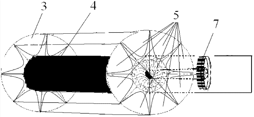
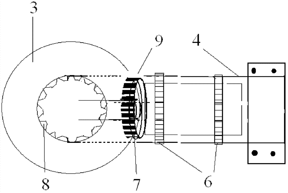
[0030] Dig a circular hole with a diameter of 65-75 centimeters in the middle of two circular load-bearing side plates 3 having the same diameter as the water wheel 1, for placing the generator. Pass the steel plate central axis cylinder 4 with the same diameter as the center hole of the load-beari...

Embodiment 2

[0037] On the basis of the first embodiment above, there is a water wheel bearing on the water wheel installation frame 2 in this embodiment; the length of the steel plate central axis cylinder 4 is greater than the distance between the two circular side plates 3, and the steel plate central axis cylinder 4 is used as the water wheel 1. The rotating shaft is erected on the water wheel mounting frame and supported by the water wheel bearing to rotate; the outer shell of the generator is used as the rotor of the generator and fixed in the central shaft cylinder 4; the center coil of the generator is used as the stator of the generator, and the stator Be fixed together with floating water tank 10.

[0038] The central coil of the generator is fixed with the guide device, and the rotation of the water wheel 1 will drive the shell of the generator to rotate relative to the central coil of the generator to generate electricity.

[0039] Further, on the basis of the first embodiment ...


PUM


Abstract

The invention discloses a hydraulic generator, in particular to a water flow generator, which comprises a fixed device, two diversion devices, a water wheel and a generator. The diversion devices, the water wheel and the generator are combined into a whole and are arranged on the fixed device; the two diversion devices are arranged vertical to the water flow direction and on the water level in parallel, water flow is limited so that water flows through a water flow channel between the two diversion devices, and the two diversion devices are respectively provided with a water wheel mounting frame; the water wheel axially crosses the two diversion devices and is arranged on the water wheel mounting frames, the lower part of the water wheel is immersed in water in the water flow channel, andthe center of the water wheel shaft is provided with a central cavity; and the generator is arranged in the central cavity of the water wheel, the stator of the generator is fixedly connected with the two diversion devices, and the rotor of the generator is coupled with the water wheel. The water flow generator has a simple process and a simple structure. The kinetic energy of the water flow can be converted into mechanical energy based on the principle of minimum consumption, and simple, efficient, smooth and safe operation can be achieved.

Description

technical field [0001] The invention relates to a hydraulic generator, in particular to a flowing water generator. Background technique [0002] Hydropower generation is clean and renewable, and can be used as a long-term solution to energy constraints, so it has received unprecedented attention. Compared with traditional hydropower generation, flowing water power generation technology is more advanced, not only will it not cause problems such as resettlement of immigrants, impact on the ecological environment, and huge investment caused by the construction of reservoirs. If flowing water power stations are built according to the distribution of streams in the country, more than 100,000 "10,000-kilowatt" level flowing water power stations can be built. Each power station has an investment of about 2.5-3 million yuan, and it can be put into production within 3 to 5 months. At present, the patented technology of flowing water power generation that has been researched and dev...

Claims


Application Information

Patent Timeline
Patent Type & Authority Patents(China)
IPC IPC(8): F03B13/00F03B3/18
CPCY02E10/223Y02E10/20
Inventor 滕传文滕易霏滕易坤
Owner 腾传文
Learn More