Novel cross-flow fan impeller and assembling method thereof
What is AI technical title?
AI technical title is built by PatSnap AI team. It summarizes the technical point description of the patent document.
A cross-flow fan and impeller technology, applied in the field of new cross-flow fan impeller and its assembly, can solve the problems of high wind speed, low wind speed, high noise, etc., and achieve the effects of high wind speed, increased wind interception area, and low noise
Pending Publication Date: 2021-02-02
宁波市天超通风设备有限公司
View PDF0 Cites 0 Cited by
Summary
Abstract
Description
Claims
Application Information
AI Technical Summary
This helps you quickly interpret patents by identifying the three key elements:
Problems solved by technology
Method used
Benefits of technology
Problems solved by technology
[0004] The purpose of the present invention is to provide a new cross-flow fan impeller for the defects of low wind speed and high noise in the above-mentioned prior art, which can achieve the purpose of high wind speed and low noise
Method used
Image
Click on the blue label to locate the original text in one second.
Reading with bidirectional positioning of images and text.
Examples
Embodiment 1
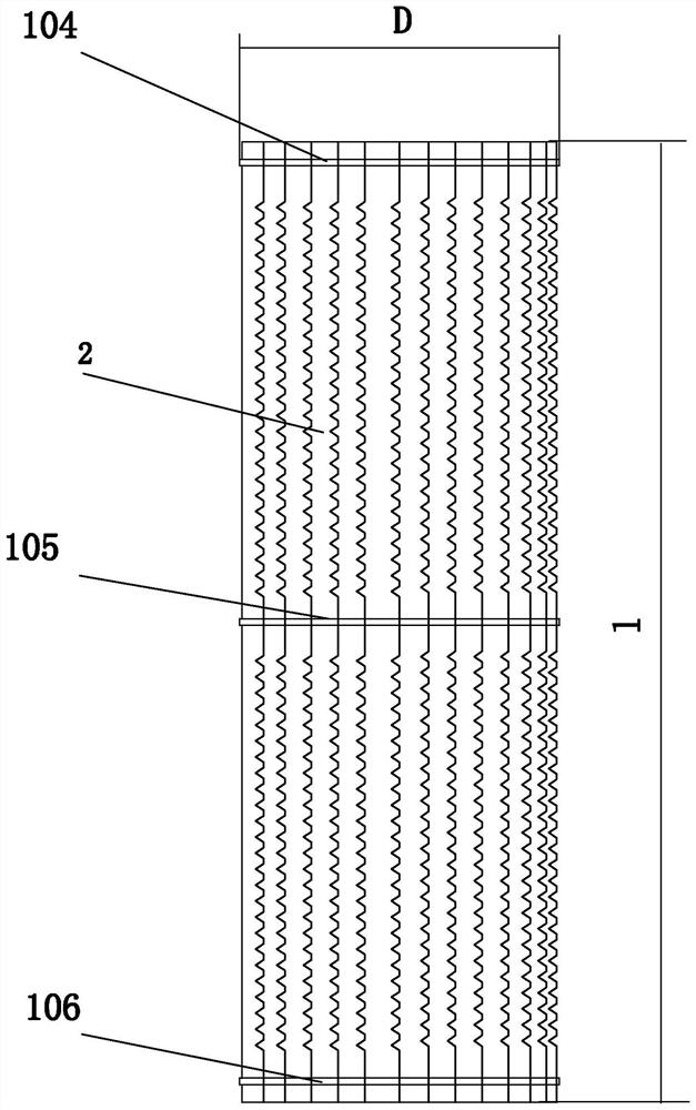
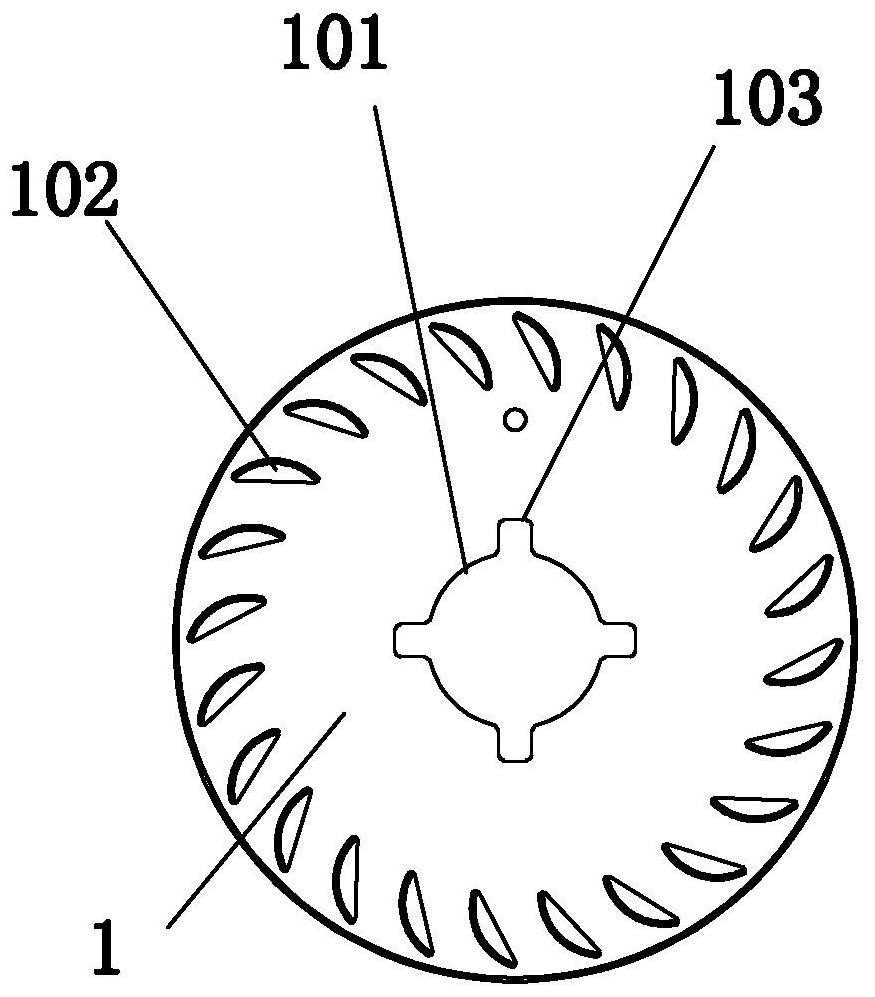
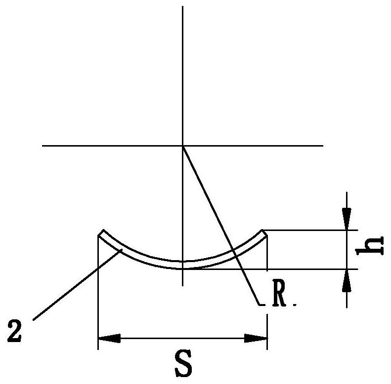
[0078] Such as Figure 1 to Figure 19 As shown, the new cross-flow fan impeller, such as Figure 1 to Figure 3 As shown, it is a barrel-shaped wheel, referred to as the impeller, including three fixed disks 1 and fan blades. The number of slot holes 102 is equal to the number of blades 2; a reference hole 101 is arranged in the middle of the fixed disk 1, and four key grooves 103 are evenly arranged around the periphery of the reference hole 101; The slotted hole, the blade 2 is a rectangular strip, installed in the blade fixing slot 102, and connects all the fixed disks 1 together; the cross section of the blade 2 is an arc section, and the width S of the arc section of the blade 2 is 7.7mm , the height h of the arc section of the blade 2 is 1.8 mm, and the arc radius R of the arc section of the blade 2 is 5.5 mm;
[0079] Such as Figure 4 to Figure 9 As shown, the blade 2 is provided with a notch 201 on the outer side, and the blade 2 between every two fixed disks 1 cont...
Embodiment 2
[0124] The notch 201 is a concave notch 201 .
[0125] Such as figure 1 with figure 2 As shown, the fixed disk 1 is a front fixed disk 104 , a middle fixed disk 105 and a rear fixed disk 106 .
[0126] Such as Figure 8 As shown, the upper convex edge 202 and the lower bottom edge 203 of the concave notch 201 of the concave notch 201 have the same length.
[0127] The equipment used is a high-speed punchingmachine, a concave notch 201 blade 2 stamping dies 7 .
[0128] The shape of the stamping die for the concave-shaped notch blade corresponds to the shape of the concave-shaped notch blade.
[0129] The rest are the same as embodiment 1.
Embodiment 3
[0131] The notch 201 is a wavy notch 201 .
[0132] Such as figure 1 with figure 2 As shown, the fixed disk 1 is a front fixed disk 104 , a middle fixed disk 105 and a rear fixed disk 106 .
[0133] Such as Figure 9 As shown, the shape and size of the upper wavy line 204 and the lower wavy line 205 of the wavy gap 201 are equal, and the upper wavy line 204 and the lower wavy line 205 are opposite in direction, connected to each other, and intersected.
[0134] The equipment used is a high-speed punchingmachine, a wave-shaped notch 201 blade 2 stamping die 7.
[0135] The shape of the stamping die of the wavy notch blade corresponds to that of the wavy notch blade.
[0136] The rest are the same as embodiment 1.
PUM
Abstract
The invention provides a novel cross-flow fan impeller and an assembling method thereof, and belongs to the technical field of cross-flow fans. The novel cross-flow fan impeller comprises two or morefixing discs and fan blades, wherein the fan blades comprise a plurality of blade bodies; a plurality of blade fixing groove holes are evenly formed in the periphery of each fixing disc; the number ofthe blade fixing groove holes is equal to that of the blade bodies; a datum hole is formed in the middle of each fixing disc; four key grooves are evenly formed in the periphery of each datum hole; the blade fixing groove holes are groove holes obliquely cut in the circumferential direction of the edge of each fixing disc; the blade bodies are rectangular strip-shaped bodies and are installed inthe blade fixing groove holes to connect all the fixing discs together; the section of each blade body is an arc-shaped section, the width of the arc-shaped section of each blade body is 7mm or above,the height of the arc-shaped section of each blade body is 1mm or above, and the arc radius of the arc-shaped section of each blade body is 5mm or above; a notch is formed in the outward side of eachblade body; the blade bodies between every two fixing discs comprise 20 or more notches; and the notches are V-shaped notches or concave notches or wavy notches. The novel cross-flow fan impeller hasthe beneficial effects that the wind intercepting area is increased, the wind speed is high, and noise is low.
Description
technical field [0001] The invention relates to a cross-flow fan impeller and an assembly method thereof, in particular to a novel cross-flow fan impeller and an assembly method thereof, and belongs to the technical field of cross-flow fans. Background technique [0002] With the rapid development of modern society and the improvement of people's living standards, the demand for all kinds of air conditioners, heaters, air curtains and other cooling and heating equipment in homes, offices and public places has increased significantly. The cross-flow impeller is one of the most important components in heating equipment such as air conditioners, heaters, and air curtains, and plays a key role in the air circulation of temperature differences. [0003] However, in the structure of the existing heating and cooling equipment, the side surfaces of the blades of the cross-flow impellers are in a straight state, the wind speed is low, and the noise is large, which needs to be solved....
Claims
Application Information
Patent Timeline
Application Date:The date an application was filed.
Publication Date:The date a patent or application was officially published.
First Publication Date:The earliest publication date of a patent with the same application number.
Issue Date:Publication date of the patent grant document.
PCT Entry Date:The Entry date of PCT National Phase.
Estimated Expiry Date:The statutory expiry date of a patent right according to the Patent Law, and it is the longest term of protection that the patent right can achieve without the termination of the patent right due to other reasons(Term extension factor has been taken into account ).
Invalid Date:Actual expiry date is based on effective date or publication date of legal transaction data of invalid patent.

