
Ethernet interface protection method and network side equipment

A network-side device and interface protection technology, applied in the communication field, can solve the problems of low switching performance, poor scalability and compatibility of edge devices, and large time overhead, so as to improve scalability and compatibility, reduce packet loss time, The effect of improving performance

Active Publication Date: 2011-12-21
ZTE CORP
View PDF4 Cites 12 Cited by
  • Summary
  • Abstract
  • Description
  • Claims
  • Application Information

AI Technical Summary

Problems solved by technology

However, in the prior art, in the case of cross-hop and multi-device routing, the time overhead for transmitting detection messages across hops and multi-device is large, the switching performance is not high, and the detection needs to be supported by the interconnected device, resulting in edge devices (network side equipment) poor scalability and compatibility

Method used


Image

  • Ethernet interface protection method and network side equipment
  • Ethernet interface protection method and network side equipment
  • Ethernet interface protection method and network side equipment

Examples


Embodiment Construction

[0041] In order to make the object, technical solution and advantages of the present invention clearer, the present invention will be further described in detail below in conjunction with the accompanying drawings and embodiments. It should be understood that the specific embodiments described here are only used to explain the present invention, not to limit the present invention.

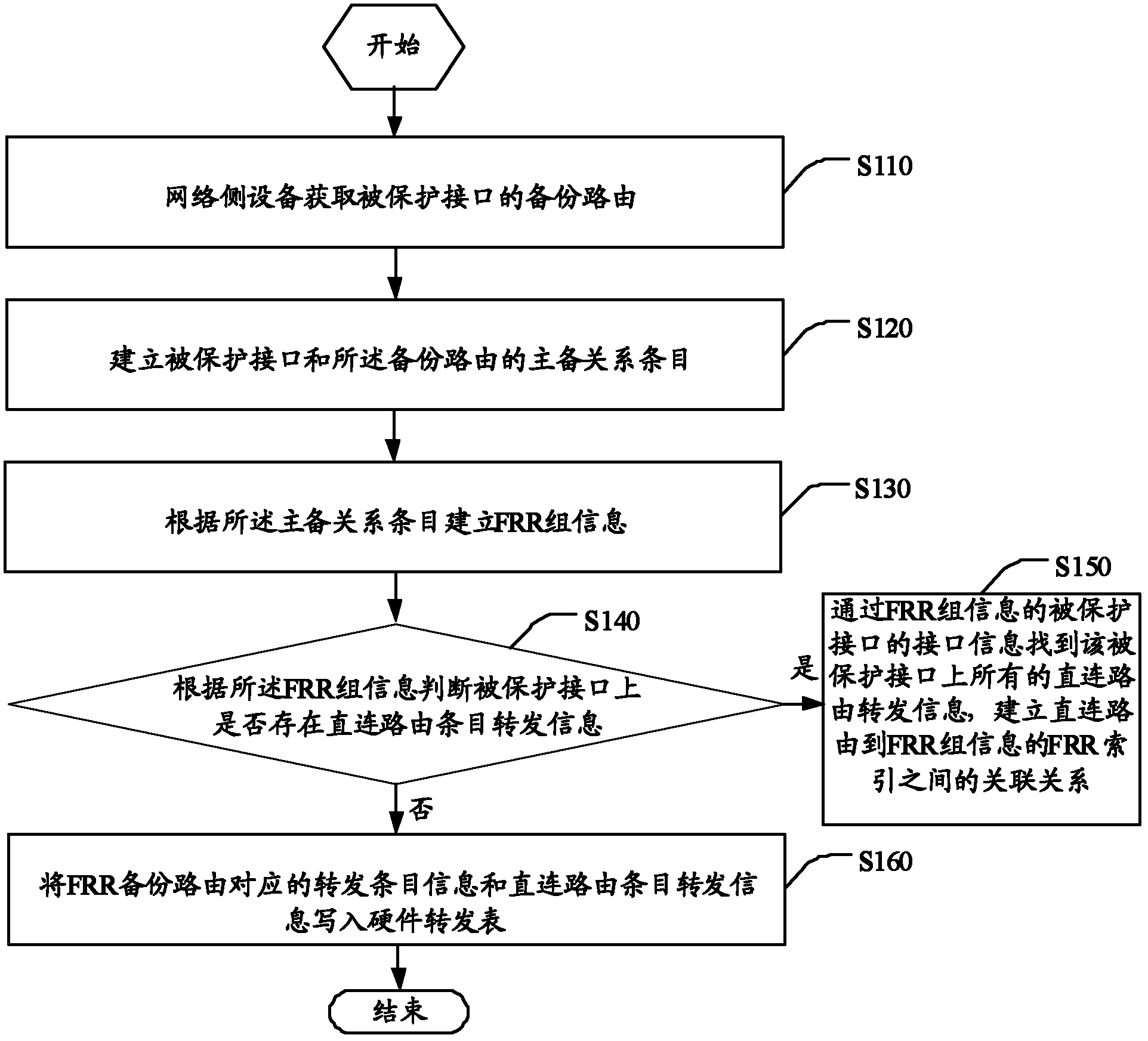
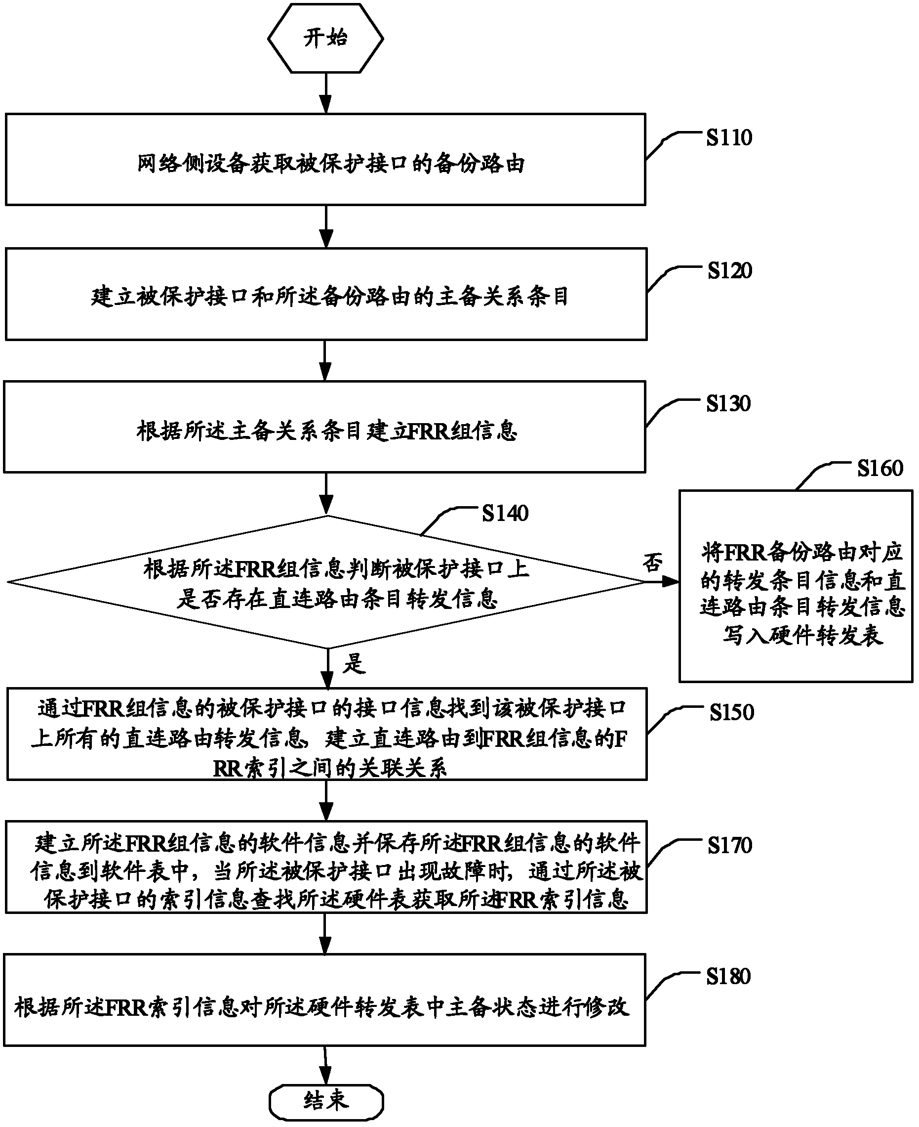
[0042] An embodiment of the present invention provides a method for protecting an Ethernet interface, such as figure 2 As shown, the method includes the steps of:

[0043] S110. The network side device obtains the backup route of the protected interface.

[0044] In this step S110, specifically, the network side device specifies the backup route of the protected interface through an OAM command, or generates the backup route of the protected interface through a protocol.

[0045] S120. Establish an active-standby relationship entry between the protected interface and the backup route.

[0046]S...


PUM


Abstract

An Ethernet interface protection method and a network side device. The method comprises: a network side device acquiring a backup route of a protected interface; establishing an active and standby relationship entry of the protected interface and the backup route; establishing FRR group information according to the active and standby relationship entry; determining, according to the FRR group information, whether directly connected route forwarding entry information exists on the protected interface; if the directly connected route forwarding entry information exists, finding all directly connected route forwarding entry information on the protected interface according to index information of the protected interface of the FRR group information, and establishing an association relationship between directly connected routes and FRR indexes of the FRR group information; and if the directly connected route forwarding entry information does not exist, writing forwarding entry information corresponding to an FRR backup route and the directly connected route forwarding entry information into a hardware forwarding table. The method can reduce a time overhead of packet detection, thereby reducing the packet loss time and improving the expansibility and compatibility.

Description

technical field [0001] The invention relates to the technical field of communication, in particular to an Ethernet interface protection method and network side equipment. Background technique [0002] Based on the requirements of rapid network development, when any node or route in the network fails, the service switching requirement is less than 50ms. For the routing between PE (Provider Edge, service provider edge device) and CE (Customer Edge, user-side edge device), VPN FRR (Virtual Private Network Fast Re-route, virtual private network-based fast rerouting) technology is mainly used to solve the problem. In the event of a node or route failure, the route can be quickly switched. [0003] The process of VPN FRR technology is: establish an end-to-end service between PE (or CE) and PE (or CE), and pre-configure two end-to-end available routes, select one as the main route, and the other as the backup routing. If the detection mechanism is not configured, protocol conver...

Claims


Application Information

Patent Timeline
Patent Type & Authority Applications(China)
IPC IPC(8): H04L12/56H04L12/24H04L45/24
CPCH04L12/4641H04L45/22H04L45/28H04L12/40045H04L45/247
Inventor 李小利
Owner ZTE CORP
Features
  • Generate Ideas
  • Intellectual Property
  • Life Sciences
  • Materials
  • Tech Scout
  • Unparalleled Data Quality
  • Higher Quality Content
  • 60% Fewer Hallucinations
Learn More