heat exchanger

A technology of heat exchangers and fluids, applied in heat exchange equipment, heat exchanger shells, indirect heat exchangers, etc., can solve the problem of inability to completely prevent air accumulation, instability of bubble generation parts, and failure of cooling water and external air Efficient heat exchange and other issues

Active Publication Date: 2011-12-21
KOMATSU LTD
View PDF2 Cites 1 Cited by
  • Summary
  • Abstract
  • Description
  • Claims
  • Application Information

AI Technical Summary

Problems solved by technology

[0007] However, looking at radiators used for engine cooling water of dump vehicles, it can be seen that when the vehicle tilts left and right due to driving on bad roads, etc., the accumulated air in the upper tank of the radiator will Inclined with the liquid level of the cooling water
Even with the structure of Patent Document 1, air cannot be reliably guided to the cooling water injection port
In addition, even in the case of adopting the structure of Patent Document 2, the generation of air pockets cannot be completely prevented due to the inclination of the liquid surface, which destabilizes the generation of air bubbles.
[0008] If the liquid level of the cooling water in the upper tank is inclined, the connecting pipe connecting the upper tank and the core is also exposed to the accumulated air, so the accumulated air will be sucked into the core of the radiator through the connecting pipe, thereby generating cooling water The problem that the core cannot perform efficient heat exchange with the outside air

Method used


Image

  • heat exchanger
  • heat exchanger
  • heat exchanger

Examples


Embodiment Construction

[0022] An embodiment of the present invention will be described below with reference to the drawings.

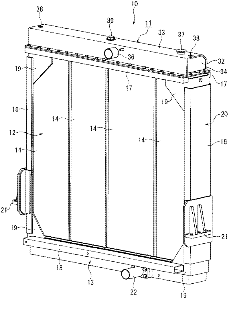
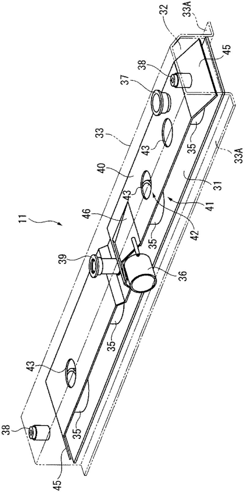
[0023] figure 1 It is a perspective view showing the whole radiator (heat exchanger) 10 according to this embodiment. The radiator 10 is used to cool the cooling water (fluid to be heat-exchanged) of the engine mounted on a large dump vehicle, etc., and it is configured as a vertical flow structure, with an upper tank 11 into which the cooling water from the engine flows, and through Heat exchange between the cooling water flowing inside the upper case 11 and the outside air The core 12 that cools the cooling water, and the lower case 13 that collects the cooling water flowing out of the core 12 and returns it to the engine side water pump of. The upper case 11 will be described later.

[0024] In the present embodiment, the core 12 is constituted by a plurality of (four in the present embodiment) module cores 14 arranged side by side in the horizontal direction. Since t...


PUM


Abstract

The invention discloses a heat exchanger. Disclosed is a radiator (10) as the heat exchanger, comprised of an upper tank (11) to which cooling water is introduced; a core (12) in which fluid from the upper tank (11) is heat-exchanged; and a lower tank (13) in which fluid from the core (12) is concentrated, wherein a baffle plate (40) is provided within the upper tank (11); and a bent portion (45)is provided at an end of the baffle plate (40) in the longitudinal direction. The baffle plate (40) divides the inner space of the upper tank (11) into two spaces, i.e., a lower space (41) and an upper space (42), and has a communication opening (43) through which the lower space (41) is communicated with the upper space (42). The bent portion (45) is bent toward the lower space (41)at the two end parts of the length direction of the baffle plate (40).

Description

technical field [0001] The present invention relates to a heat exchanger, for example, to a heat exchanger typified by a radiator. Background technique [0002] Conventional heat exchangers such as radiators, oil coolers, intercoolers (external coolers), and the like generally employ structures that suppress air stagnation in the heat exchangers (Patent Documents 1 and 2). [0003] What is described in Patent Document 1 is a water-cooled intercooler. In this intercooler, the following structure is adopted: an upwardly expanding groove is provided on the upper surface of the box into which the cooling water flows, and the cross section of the groove is arc-shaped. The air in the case is guided to the cooling water injection port through the groove, and discharged to the outside from there. [0004] What is described in Patent Document 2 is a cross-flow oil cooler, in which the following structure is adopted: the gap between the cover body of the head pipe and the pipe is red...

Claims


Application Information

Patent Timeline
IPC IPC(8): F28F9/02F28D1/053F28F9/22F28F9/24F28F9/06
CPCF28D2021/0094F28F9/0217F01P3/18F01P11/028F28F9/0214F28F9/0231F28F2265/18
Inventor 增田秀基水谷周平
Owner KOMATSU LTD
Why Eureka
Try Eureka