Connection joint for steel tube and angle steel in steel tube tower of transmission line

A steel pipe and connection type technology for transmission lines, applied in towers, building types, buildings, etc., can solve the problem of high construction cost of steel pipe towers, achieve the effects of high node stiffness, ensure effective force transmission, and reduce construction costs

Active Publication Date: 2014-03-12
CHINA ELECTRIC POWER RES INST +1
View PDF4 Cites 0 Cited by
  • Summary
  • Abstract
  • Description
  • Claims
  • Application Information

AI Technical Summary

Problems solved by technology

[0002] With the continuous improvement of the voltage level of transmission lines and the application of multi-circuit lines on the same tower, the trend of large-scale transmission line towers is becoming more and more obvious. The use of steel pipe towers for large load towers can make full use of the strength advantages of steel pipe components, but the cost of steel pipe towers is relatively high. High, in practical use, mostly use the mixed type of angle steel and steel pipe, often the main material is all steel pipe, inclined material or auxiliary material sometimes use angle steel, the iron tower with both steel pipe and angle steel as the main material is a new type of tower, this One of the principles of material selection for the tower type is that steel pipe components are used when the main material used in the largest specification angle steel in my country can no longer meet the stress. This can optimize the cost of the tower body to a greater extent, but a key point of the tower type design And the difficulty lies in how to realize the connection structure of variable cross-section joints of variable angle steel pipes

Method used


Image

  • Connection joint for steel tube and angle steel in steel tube tower of transmission line
  • Connection joint for steel tube and angle steel in steel tube tower of transmission line
  • Connection joint for steel tube and angle steel in steel tube tower of transmission line

Examples


Embodiment 1

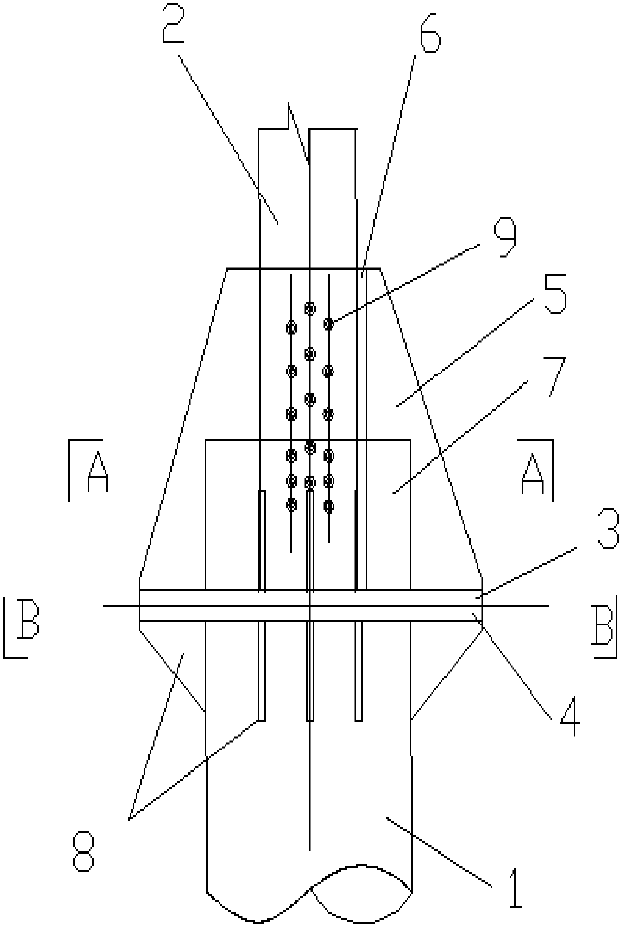
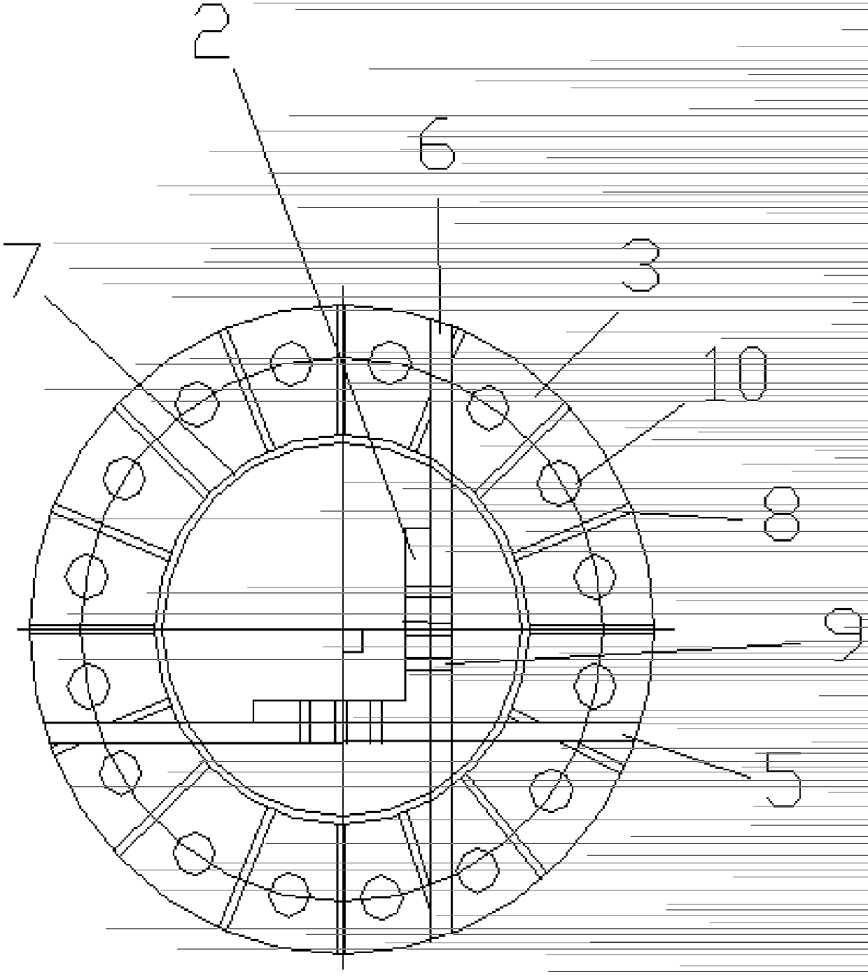
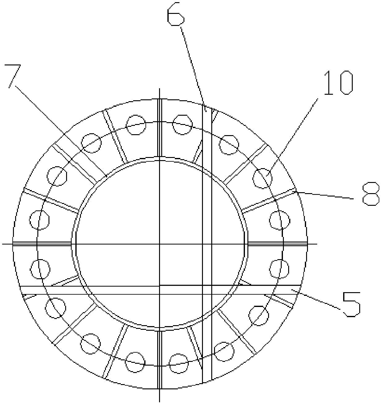
[0024] Such as Figure 1-4 As shown, the invention of this example is a connecting joint of steel pipe variable angle steel in the steel pipe tower of transmission line, including steel pipe 1, angle steel 2 and flange, and the flange is divided into upper flange 3 and lower flange with equal diameters Plate 4, one end of the upper flange 3 and one end of the lower flange 4 are connected by bolt II 10; the other end of the lower flange 4 is welded with the steel pipe 1 to form a lower flange joint, and the axial centerline of the lower flange 4 Returning to the axial center line of the steel pipe 1, a stiffening plate 8 is provided at the node connecting the lower flange 4 and the steel pipe 1, which is connected by welding. The surface of the stiffening plate 8 is perpendicular to the surface of the flange, and the stiffening plate The distribution form of 8 is as attached Figure 3-4 As shown, the stiffening plate 8 is uniformly and symmetrically distributed with the midpoi...


PUM


Abstract

The invention relates to a connection structure of a steel tube and angle steel mixed iron tower of a transmission line, and particularly relates to a connection joint of changing a steel tube into angle steel in a steel tube tower of a transmission line. The connection joint comprises a steel tube, angle steel and a flange, wherein the flange comprises an upper end flange and a lower end flange which have equal diameters, one end of the upper end flange is connected with one end of the lower end flange, the other end of the lower end flange is connected with the steel tube to form a lower end flange joint, an annular reinforcing pipe is connected to the other end of the upper end flange in the axial direction, the upper end flange and the annular reinforcing pipe form an upper end flange joint, the angle steel passes through the annular reinforcing pipe, and the angle steel is fixed by depending on a gusset plate I and a gusset plate II arranged on the upper end flange, wherein plate surfaces of the gusset plate I and the gusset plate II are mutually vertical and crossed. The connection joint is reliable in force transfer, and can be used in connection of a variable cross-section part in the steel tube and angle steel mixed iron tower.

Description

Technical field: [0001] The invention relates to a connection structure between a steel pipe of a power transmission line and a mixed iron tower of an angle steel, and more particularly relates to a connection type joint of a steel pipe variable angle steel in a steel pipe tower of a power transmission line. Background technique: [0002] With the continuous improvement of the voltage level of transmission lines and the application of multi-circuit lines on the same tower, the trend of large-scale transmission line towers is becoming more and more obvious. The use of steel pipe towers for large load towers can make full use of the strength advantages of steel pipe components, but the cost of steel pipe towers is relatively high. High, in practical use, mostly use the mixed type of angle steel and steel pipe, often the main material is all steel pipe, inclined material or auxiliary material sometimes use angle steel, the iron tower with both steel pipe and angle steel as the ma...

Claims


Application Information

Patent Timeline
Patent Type & Authority Patents(China)
IPC IPC(8): E04H12/08
Inventor 李茂华高渊
Owner CHINA ELECTRIC POWER RES INST
Why Eureka
Try Eureka