connector device

A technology of connectors and plugs, which is applied to the parts, connections, and coupling devices of connecting devices, and can solve the problems of power loss, easy disconnection, and damage of equipment.

Inactive Publication Date: 2014-10-15
SMK CO LTD
View PDF6 Cites 0 Cited by
  • Summary
  • Abstract
  • Description
  • Claims
  • Application Information

AI Technical Summary

Problems solved by technology

Not limited to this, there is also a case where the above-mentioned cable is unreasonably pulled due to some circumstances, and then, in the case where the device connected to this is a notebook computer or other portable device, etc., these devices are pulled, for example, there is There is a danger of damage due to falling
Or, sometimes destroying the connector itself
[0006] Patent Document 2 (Japanese Unexamined Patent Application Publication No. 2005-151629) relates to electrical equipment using an AC adapter, and as a conventional connector device that electrically connects both, it shows a DC connector and a DC receptacle approximately the same as those shown in Patent Document 1. The same structure, in the connector device of this structure, pointed out that there is the following problem: If the cable is pulled, the two are relatively easy to disengage, but in the case of such a pull that is not expected, the power supply of the equipment will suddenly come off, and propose a solution to the problem
However, if the holding force is too weak, the connection of the connector can be released with a very small force, which may unexpectedly cut off the connection with the signal source connected through the connector or cut off the connection with the power supply. new question

Method used


Image

  • connector device
  • connector device
  • connector device

Examples


Embodiment Construction

[0035] While referring to the attached Figure 1 Embodiments of the present invention will be described in detail.

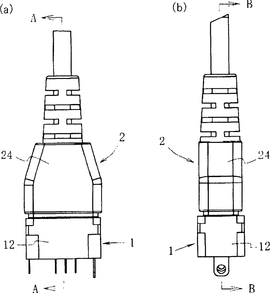
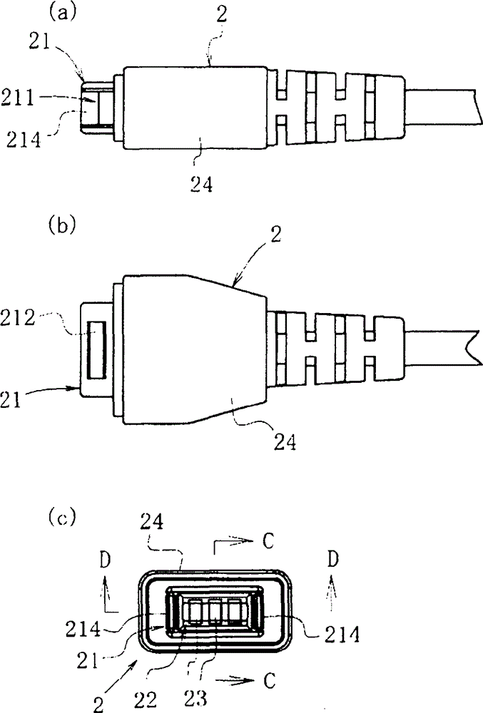
[0036] The connector device of this embodiment is basically as figure 1 (a), figure 1 (b), figure 2 (a), figure 2 (b) and Figure 7 (a), Figure 7 As shown in (b), it is a device suitable for a DC connector having a short fitting length composed of a socket 1 and a plug 2 having a fitting portion 21 inserted into the plug insertion hole 11 thereof.

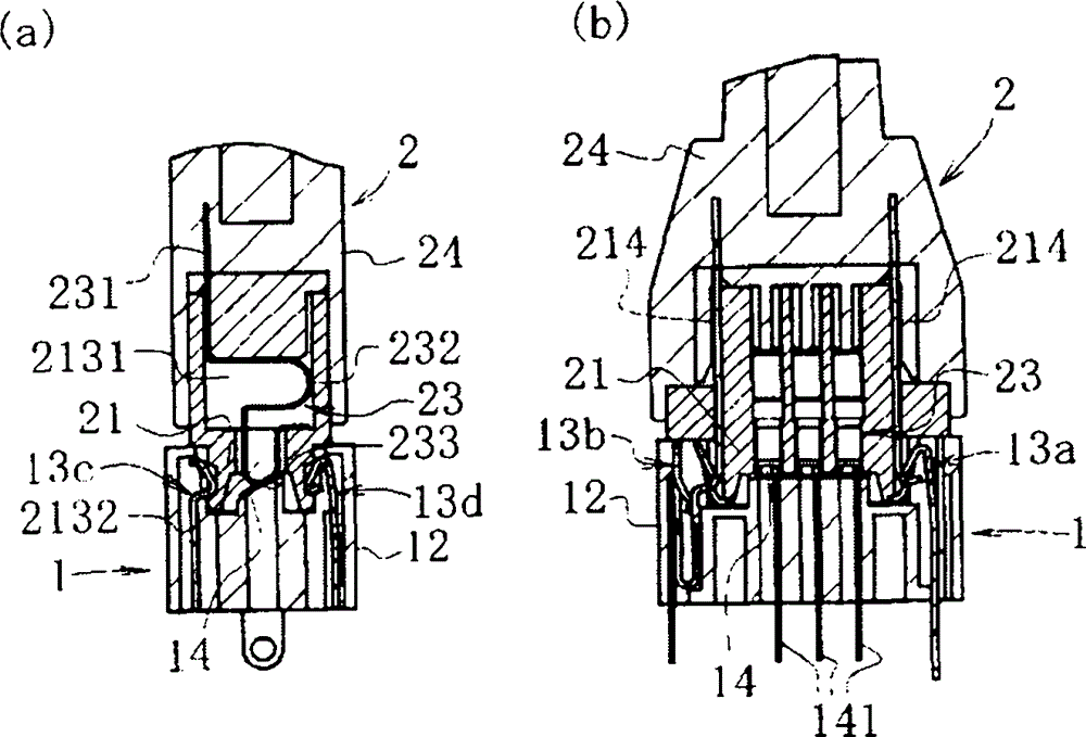
[0037] Such as Figure 5 As shown in (b), the above-mentioned socket 1 is composed of the following members: an insulating socket main body 12 having a rectangular plug insertion hole 11 with a horizontal width in a front view; Plug holding springs 13 a , 13 b , 13 c , 13 d arranged so that their surfaces protrude inward, and three terminals 14 , 14 , 14 are arranged on the bottom surface 15 which is the innermost side of the plug insertion hole 11 .

[0038] In this embodiment, if Figure 5 (a)~ Figure...


PUM


Abstract

PROBLEM TO BE SOLVED: To allow a plug or male connector of the connector device to easily come out of a jack or female connector without damaging the connector device when the plug or male connector is drawn in a direction orthogonal or oblique to the axis center thereof until the drawing force exceeds a holding force. SOLUTION: The connector device comprises a socket 1 consisting of a socket body 12 having a rectangular plug insertion hole 11 opened, plug holding springs 13a, 13c and 13d arranged on inner surfaces of four sides of the plug insertion hole 11, and three terminals 14 arrayed on a bottom surface 15 of the plug insertion hole 11, and the plug 2 consisting of a rectangular fitting portion 21, a plug body 24 having the fitting portion protruded atop, lock recess portions 211 and 212 on outer surfaces of four sides of the fitting portion 21 that the plug holding springs 13a, 13c and 13d are locked to, and a contact piece spring 23 arrayed on a bottom surface of a hollow portion of the fitting portion 21 to come into contact with the terminals 14 when the plug is fitted. COPYRIGHT: (C)2012,JPO&INPIT

Description

technical field [0001] The present invention relates to a connector device for electrically connecting various cables for transmitting electric signals or supplying electric power, and for outputting and receiving the electric signals or electric power. Background technique [0002] Among such connector devices, there is an example of a connector device including a DC connector (plug) and a DC receptacle disclosed in Patent Document 1 (Japanese Patent Laid-Open No. 2004-171848). Patent Document 1 is titled as a portable electronic device, but its substance relates to a connector device, which is an improved device so as to prevent a DC connector of an incompatible size from being inserted and arranged in a wrong or other reason. In the case of a DC receptacle on a device, the central terminal pin arranged in the DC receptacle is forcibly pushed in the back direction and falls out into the device. [0003] The DC socket and the corresponding DC connector basically do not cha...

Claims


Application Information

Patent Timeline
Patent Type & Authority Patents(China)
IPC IPC(8): H01R13/639H01R31/06
Inventor 樱田英将笹木仁人
Owner SMK CO LTD
Why Eureka
Try Eureka