
status display device

A state display, state technology, applied in static indicators, instruments, electrical digital data processing and other directions, can solve the problem of time-consuming and achieve the effect of easy verification

Inactive Publication Date: 2011-12-28
MITSUBISHI ELECTRIC CORP
View PDF9 Cites 2 Cited by
  • Summary
  • Abstract
  • Description
  • Claims
  • Application Information

AI Technical Summary

Problems solved by technology

At this time, when using the display device of the built-in device for checking the GUI screen, a time-consuming operation of temporarily transferring the GUI application created on the personal computer to the built-in device and trying to display it is generated.

Method used


Image

  • status display device
  • status display device
  • status display device

Examples


Embodiment approach 1

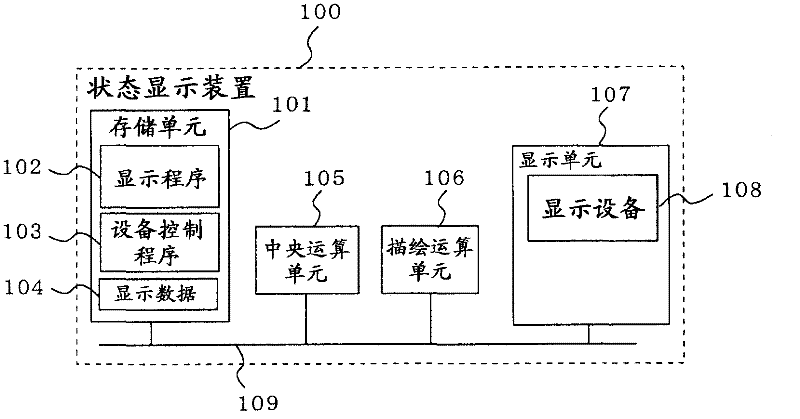
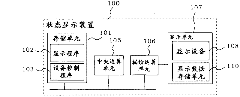
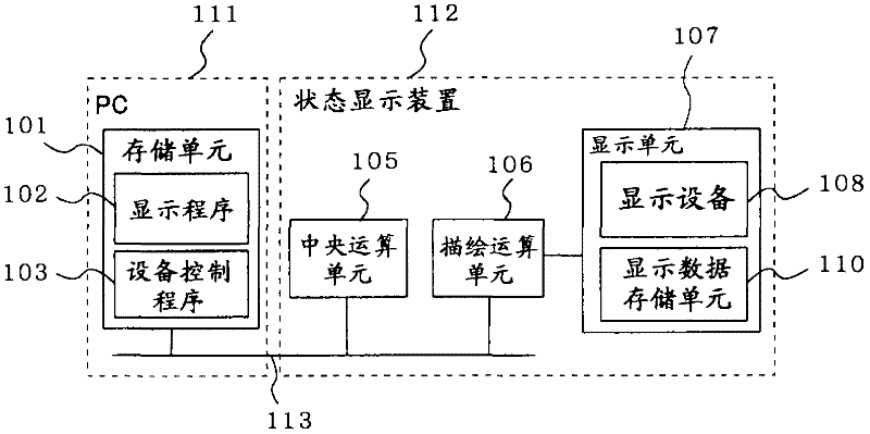
[0026] figure 1 , figure 2 , image 3 , Figure 4 , Figure 5 , Image 6 , Figure 7 as well as Figure 8 It is a diagram showing an example of a schematic configuration of the state display device according to Embodiment 1 of the present invention.

[0027] exist figure 1 , figure 2 , Figure 8 as well as Figure 9 In , the structure and basic operation of this status display device will be described.

[0028] The status display device 100 is composed of a central processing unit 105, a drawing computing unit 106, a display unit 107, and a storage unit 101, and the storage unit 101 stores a display program 102, a device control program 103, and display data 104.

[0029] Assuming that the display device 108 of the display unit 107 is a full-point liquid crystal, use figure 1 , Figure 8 , Figure 9 Describe the action.

[0030] The display unit 107 emits light at high speed according to the movement of the display position from the upper left to the right and...


PUM


Abstract

The present invention provides a highly efficient development environment that can easily verify the performance, processing load, and display status of an embedded device and shorten the cycle time of development. It includes a display unit (107), a central operation unit (105), a rendering operation unit (106), and a storage unit (101). The central operation unit (105) interprets the content described in the command address in the storage unit (101) at each predetermined operation unit clock, and performs various operation processes. The rendering operation unit (106) shares the memory unit (101) with the central operation unit (105) and performs rendering operation processing. The display unit (107) and the rendering operation unit (106) share the specified storage space starting with the display address in the storage unit (101), and display on the display device ( 108) on. Furthermore, it is allowed to provide the storage unit (101) and / or the central processing unit (105) outside the status display device.

Description

technical field [0001] The present invention relates to a state display device and a state display method for displaying the state of equipment such as an air conditioner and electronic equipment. Background technique [0002] With the multifunctionalization of electronic equipment such as air conditioners and home appliances, it is impossible to operate the equipment only by conventional display devices with fixed content directly connected to a plurality of buttons, such as segmented liquid crystal displays. Therefore, recently, devices have been manufactured that display arbitrary graphics and images using general-purpose liquid crystals (so-called full-point liquid crystals) that are gradually becoming cheaper, and then use their properties to switch screen displays or combine small window-like ones for explanations. Window display method (so-called Graphical User Interface: GUI) to achieve both versatility and ease of use. For the user, operability such as being able t...

Claims


Application Information

Patent Timeline
Patent Type & Authority Applications(China)
IPC IPC(8): G06F11/28
CPCG09G3/006G06F11/324G06F3/1415
Inventor 小宫纪之久代纪之中田成宪胜仓真
Owner MITSUBISHI ELECTRIC CORP
Learn More