Steel rolling motor shaft shoulder end face movable turning device

A technology of motor shaft and end face, which is applied to turning equipment, turning equipment, metal processing machinery parts, etc., can solve the problems of time-consuming, affecting production, high cost, etc., and achieve the effect of cost saving and convenient disassembly

Active Publication Date: 2013-08-07
XIANGTAN ELECTRIC MFG CORP LTD
View PDF4 Cites 0 Cited by
  • Summary
  • Abstract
  • Description
  • Claims
  • Application Information

AI Technical Summary

Problems solved by technology

Method 1 in the past was to remove the upper bearing cover, upper bearing bush and thrust bush of the thrust bearing, expose half of the motor shaft shoulder end face, start the frequency conversion speed regulation synchronous rolling steel motor to rotate, and polish it with abrasive cloth and oil stone, which is time-consuming It is laborious, and the flatness required by the technology cannot be achieved; the past method 2 is to disassemble the motor and send it back to the manufacturer for repair, which is too expensive, time-consuming, and affects production

Method used


Image

  • Steel rolling motor shaft shoulder end face movable turning device
  • Steel rolling motor shaft shoulder end face movable turning device
  • Steel rolling motor shaft shoulder end face movable turning device

Examples


Embodiment Construction

[0022] The present invention will be further described below in conjunction with accompanying drawing. The technical solutions in the embodiments of the present invention are clearly and completely described. Obviously, the described embodiments are only some of the embodiments of the present invention, not all of them. Based on the embodiments of the present invention, all other embodiments obtained by persons of ordinary skill in the art without making creative efforts belong to the protection scope of the present invention.

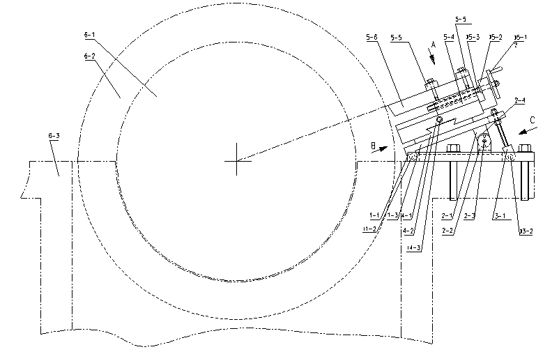
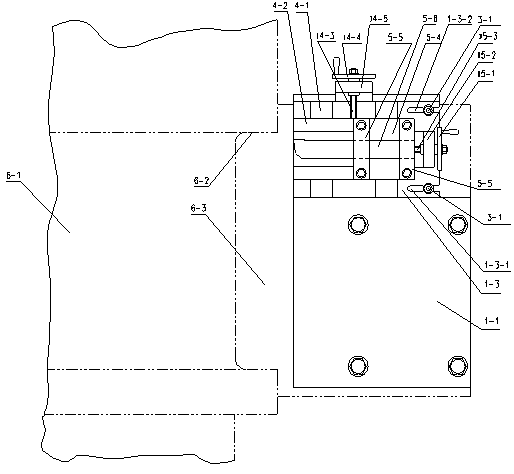
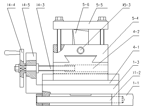
[0023] refer to figure 1 , figure 2 , image 3 , Figure 4 , Figure 5 : figure 1 , figure 2 It is a structural diagram of removing the sliding thrust bearing at one end of the motor, the upper half of the bearing cover, the upper bearing bush and the upper thrust bush at the end, and the lower half. Knife device, longitudinal feeding device, characterized in that the straight line formed by the turning tool 5-6 tip and the center of the motor...


PUM


Abstract

The invention provides a steel rolling motor shaft shoulder end face movable turning device. The steel rolling motor shaft shoulder end face movable turning device comprises a transverse feeding device and a longitudinal feeding device; the straight line between the point of a turning tool and the center of a motor shaft is regulated to parallel to the axis line of a lead screw II, so that a motor rotates, steel rolling motor shaft shoulder end face turning can be realized on working site, time, labor and cost are saved, and the flatness and the roughness of the technical requirements can be ensured; and because the steel rolling motor shaft shoulder end face movable turning device is movably arranged on the plane of a bearing seat and a bottom plate is fixed by using screw holes in the plane of the bearing seat, the device is convenient for disassembly and assembly.

Description

technical field [0001] The invention relates to a device for turning a motor shaft in a working condition, in particular to a movable turning device for a shaft shoulder end face of a steel rolling motor. Background technique [0002] The thrust tile on the thrust bearing that is in contact with the shaft shoulder end surface of the rolled steel motor is worn due to operation, resulting in unevenness and groove marks on the shaft shoulder end surface of the motor, which needs to be repaired and smoothed. Method 1 in the past was to remove the upper bearing cover, upper bearing bush and thrust bush of the thrust bearing, expose half of the motor shaft shoulder end face, start the frequency conversion speed regulation synchronous steel rolling motor to rotate, and polish it with abrasive cloth and oil stone, which is time-consuming It is laborious, and the flatness required by the technology cannot be achieved; the past method 2 is to disassemble the motor and transport it bac...

Claims


Application Information

Patent Timeline
Patent Type & Authority Patents(China)
IPC IPC(8): B23B5/08B23Q1/25B23Q1/01
Inventor 秦爱国姚建荣李春林樊晓陈首衡
Owner XIANGTAN ELECTRIC MFG CORP LTD
Why Eureka
Try Eureka