Screwing-in anchoring device for crane

A technology for anchoring devices and cranes, which is applied in the directions of safety devices, transportation and packaging, and load hanging components, etc. Reliable, compact structure, scientific and reasonable design

Active Publication Date: 2012-01-04
DALIAN HUARUI HEAVY IND GRP CO LTD
View PDF8 Cites 7 Cited by
  • Summary
  • Abstract
  • Description
  • Claims
  • Application Information

AI Technical Summary

Problems solved by technology

The above-mentioned traditional type of anchoring device has the following disadvantages and deficiencies: it can only achieve anchoring in the horizontal direction, but cannot achieve anchoring in the vertical direction. accidents; and during the operation of the crane, each part of the anchoring device is likely to shake due to the vibration of the crane

Method used


Image

  • Screwing-in anchoring device for crane
  • Screwing-in anchoring device for crane
  • Screwing-in anchoring device for crane

Examples


Embodiment Construction

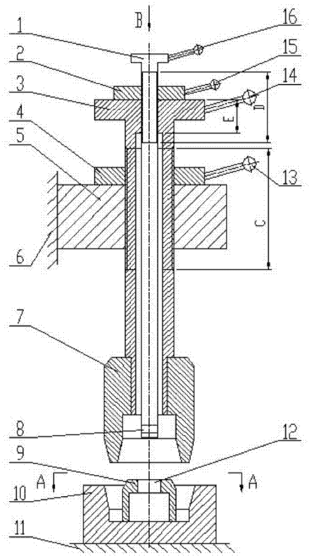
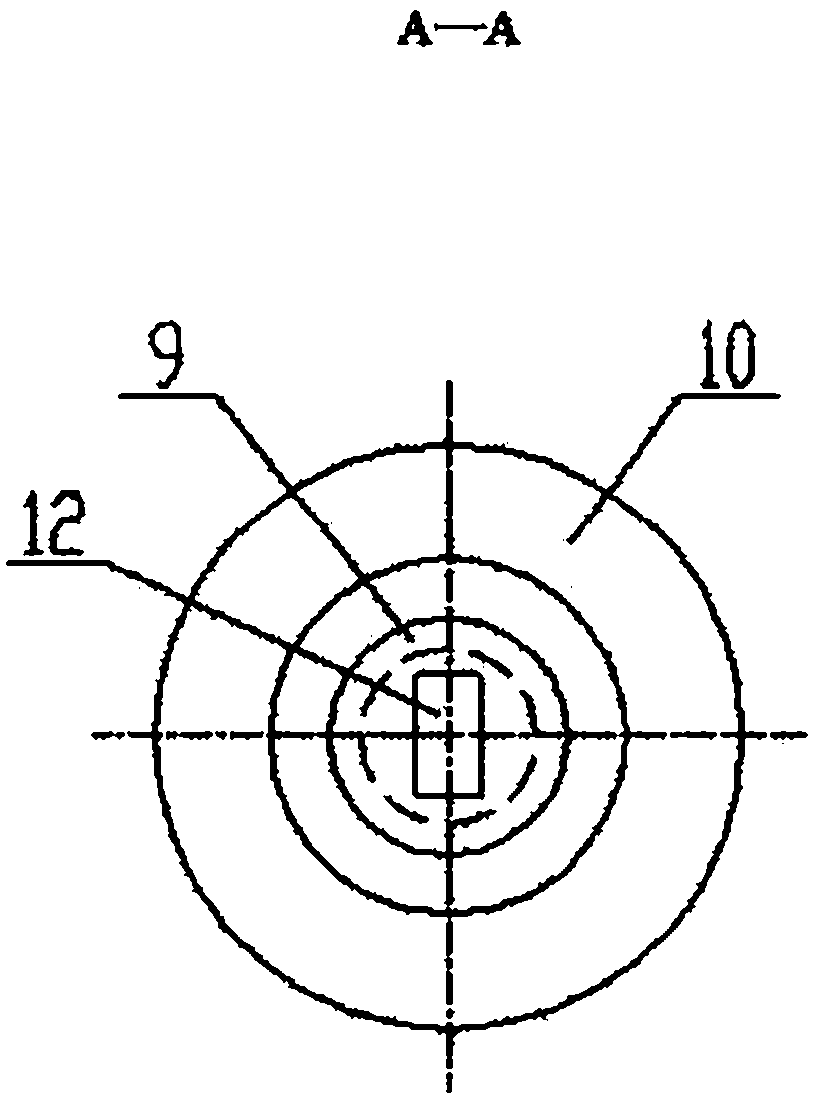
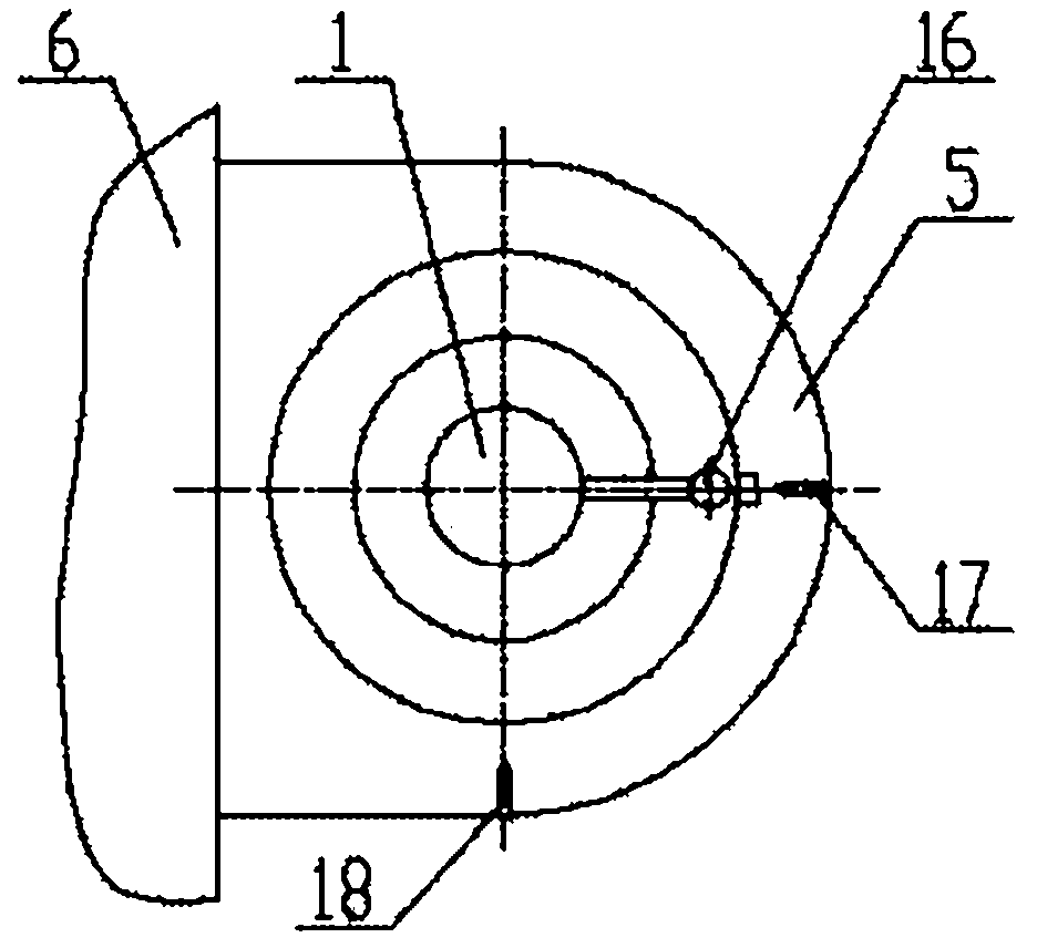
[0017] figure 1 , 2 Shown is a specific embodiment of the present invention; it is a crane screw-in type anchoring device installed on a nuclear power fuel crane; it is characterized in that: a screw-in type anchoring device is installed on the trolley frame 6 of the crane, the described The anchoring device consists of support plate 5, A mark 17, B mark 18, hollow screw 3, guide cone head 7, inner screw 1, small nut 2, large nut 4, square locking block 8, locking sleeve 9 and guide cone 10 components, the support plate 5 is connected on the side of the trolley frame 6, and the top surface of the support plate 5 is respectively equipped with A mark 17 and B mark 18 with an angular distance of 90°, and the support plate 5 is threaded Connect the hollow screw 3, the two ends of the hollow screw 3 are exposed outside the support plate 5, the bottom end of the hollow screw 3 is connected to the guide cone 7, and the top of the hollow screw 3 is a flange head, in this method The ...


PUM


Abstract

The invention belongs to a crane apparatus, and in particular relates to a screwing-in anchoring device for a crane which is suitable for the nuclear power with high safety requirements. The screwing-in anchoring device is characterized in that a trolley frame of the crane is equipped with the screwing-in anchoring device consisting of a supporting plate, a mark A, a mark B, a hollow screw rod, aguide cone head, an inner screw rod, a small nut, a big nut, a square locking block, a locking bush and a guide cone. The screwing-in anchoring device is scientific and rational in design and compactin structure, can realize the anchoring of a vertical direction while holding the anchoring in a horizontal direction, is not only suitable for the protection in earthquake, but also suitable for preventing the invasion of sudden wind; and the screwing-in anchoring device has the advantages of convenience in operation, firmness in anchoring, low fault rate, safety in operation and convenience in use.

Description

technical field [0001] The invention belongs to crane equipment, in particular to a screw-in anchoring device for cranes suitable for cranes with high safety requirements such as nuclear power plants. Background technique [0002] At present, the cranes used in ports or outdoors are usually protected by installing traditional anchoring devices on the cranes; the traditional anchoring devices are divided into pin type, chain type, and push rod type. and anchor plate type, etc., and most of their structures adopt a lever structure; after patent retrieval, its patent announcement number is an anchor device of CN200910181447.2, and its structure includes a lever handle, a rotating pin shaft, a labor-saving counterweight, and an anchor plate and locking holes. The above-mentioned traditional type of anchoring device has the following disadvantages and deficiencies: it can only achieve anchoring in the horizontal direction, but cannot achieve anchoring in the vertical direction. ...

Claims


Application Information

Patent Timeline
Patent Type & Authority Applications(China)
IPC IPC(8): B66C15/00
Inventor 时军奎邢述钦杨文通张娜丁晶
Owner DALIAN HUARUI HEAVY IND GRP CO LTD
Why Eureka
Try Eureka