Pipe network pressure control system

A pipe network pressure and control system technology, which is applied in the pipeline system, mechanical equipment, gas/liquid distribution and storage, etc., can solve the problems of no discovery, energy consumption, and the inability to guarantee the adjustment accuracy of the outlet pressure of the pressure reducing valve, etc., to achieve reduction Effects of damage and loss, improvement of management, and enhancement of safe and stable operation capabilities

Active Publication Date: 2012-01-04
陶建科
View PDF3 Cites 11 Cited by
  • Summary
  • Abstract
  • Description
  • Claims
  • Application Information

AI Technical Summary

Problems solved by technology

The existing pipe network pressure control device is usually composed of a pressure reducing valve and a pipeline. By manually adjusting the outlet pressure of the pressure reducing valve, the pressure at the lower part of the pipe network pressure can meet the requirements and maintain a stable pressure at the outlet of the pressure reducing valve. However, due to this There are insurmountable shortcomings in the structure and the way of manually adjusting the outlet pressure of the pressure reducing valve. The outlet pressure cannot be adjusted in real time according to the changes in the water demand of users in the downstream pipe network at the outlet of the pressure reducing valve, etc.
[0004] At present, my country is engaged in water pipe network, sewage pipe network, oil pipeline and gas pipe network, automatic dynamic pressure control, using electronic components to achieve products, has not yet found

Method used


Image

  • Pipe network pressure control system
  • Pipe network pressure control system
  • Pipe network pressure control system

Examples


Embodiment 1

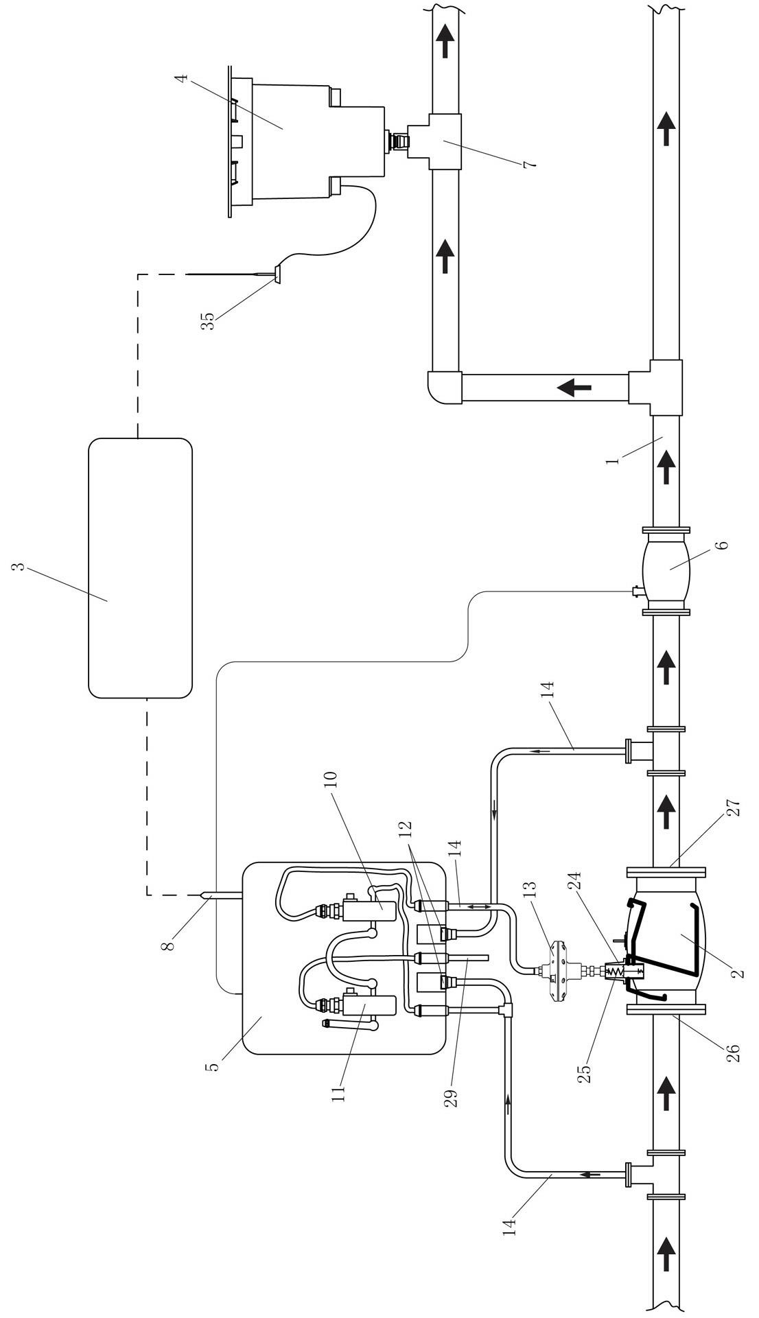
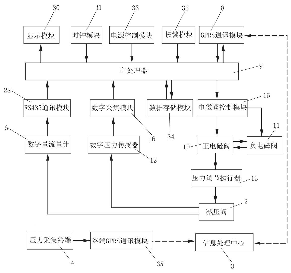
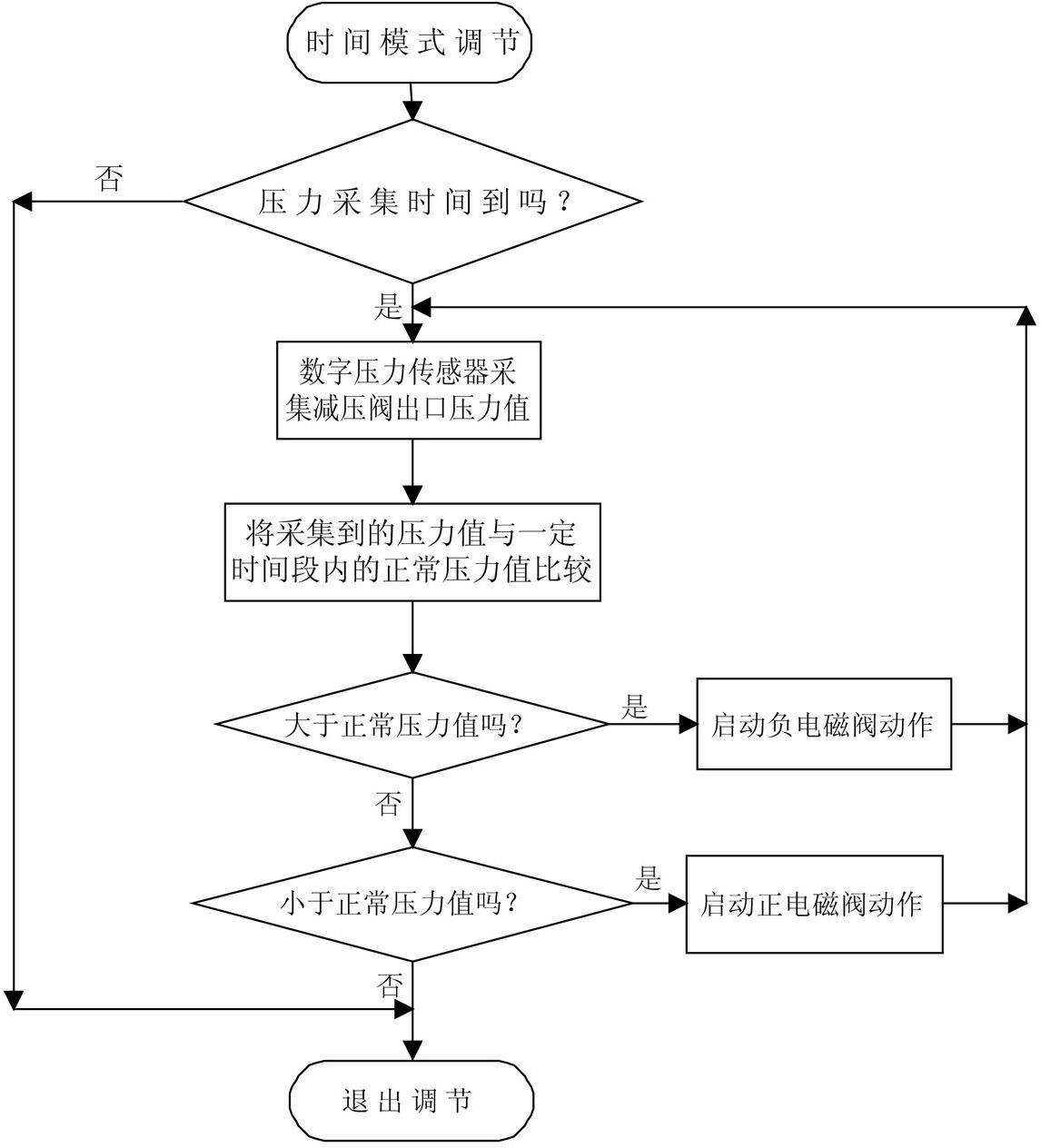
[0035] Embodiment 1: In this example, the control mode of the main processor 9 of the pressure controller 5 adopts the time mode.

[0036] 1) After setting the control mode of the main processor 9 to the time mode through the key module, the main processor 9 sets 7 pairs of normal pressure values ​​within a certain period of time (one time period corresponds to one pressure value, which is regarded as a pair), and a certain period of time The corresponding relationship between the time period and the normal pressure value is: when the time period is 0~7 o’clock (excluding 7 o’clock), the normal pressure value is 0.35Mpa; when the time period is 7~9 o’clock (excluding 9 o’clock), The normal pressure value is 0.5Mpa; when the time period is 9~11 o'clock (excluding 11 o'clock), the normal pressure value is 0.4Mpa; when the time period is 11~13 o'clock (excluding 13 o'clock), the normal pressure value is 0.5Mpa; when the time period is 13~17 o'clock (excluding 17 o'clock), the norma...

Embodiment 2

[0042] Embodiment 2: In this example, the control mode of the main processor 9 of the pressure controller 5 adopts the flow mode.

[0043] A. After the information processing center sets the main processor 9 to the flow mode through the RS485 communication module, the main processor 9 sets 3 to the normal pressure value in a certain flow section, and the corresponding relationship between the certain flow section and the normal pressure value is respectively: When the flow rate is 20~25 cubic meters / hour (excluding 25 cubic meters / hour), the normal pressure value is 0.35Mpa; when the flow rate is 25~30 cubic meters / hour (excluding 30 cubic meters / hour), the normal pressure The value is 0.4Mpa; when the flow rate is 30~35m3 / h (excluding 35m3 / h), the pressure is 0.5Mpa. When setting the flow section, the flow section can be segmented according to the actual situation. For example, take the flow rate of 5 cubic meters per hour to 50 cubic meters per hour as an example, and take ...


PUM


Abstract

The invention discloses a pipe network pressure control system. The pipe network pressure control system comprises a pipe network, a pressure reducing valve, a pressure controller, a pressure acquisition terminal and an information processing center, wherein the pressure controller and the pressure acquisition terminal are connected with the information processing center in a wireless communication mode respectively; the pressure controller mainly comprises a main processor, a wireless communication module, an electromagnetic valve, a digital pressure sensor, a pressure adjustment actuator used for adjusting the pressure of the pressure reducing valve, and a hose hoop consisting of hoses; and the main processor controls the electromagnetic valve to perform positive or negative adjustment by comparing a normal pressure value with a pressure value of an outlet of the pressure reducing valve so as to control the pressure adjustment actuator to adjust the pressure of the outlet of the pressure reducing valve. The pipe network pressure control system has the advantages of grasping the dynamic operational parameter condition of the pipe network in real time, dynamically optimizing and stably adjusting the pressure of the pipe network when demands are changed, improving the management, check and maintenance levels of the pipe network, improving the safe and stable running capacity of the pipe network, and the like.

Description

technical field [0001] The invention relates to a pipe network pressure control device, in particular to a pipe network pressure control system. Background technique [0002] For the water pipe network, pressure control is the simplest and immediate method to reduce the leakage of the pipe network and reduce the frequency of pipe bursts. [0003] When there is no electronic control, the pressure reducing valve must be set at the "most unfavorable" point where the pressure of the pipe network is low and easy to change. Under the condition of maximum flow, the key point in the pipe network (usually the highest point ) minimum pressure. At lower flow rates, this setting will result in a higher pressure than required. The existing pipe network pressure control device is usually composed of a pressure reducing valve and a pipeline. By manually adjusting the outlet pressure of the pressure reducing valve, the pressure at the lower part of the pipe network pressure can meet the r...

Claims


Application Information

Patent Timeline
IPC IPC(8): F17D3/01
Inventor 陶建科
Owner 陶建科
Why Eureka
Try Eureka