Equipment state detecting method used for thermal power plant

A technology for thermal power plants and detection methods, which is applied in measurement devices, data processing applications, instruments, etc., can solve problems such as inability to detect equipment status information, unfavorable overall status of equipment, and inability to obtain different index relationships.

Inactive Publication Date: 2012-01-04
CHINA SHENHUA ENERGY CO LTD +3
View PDF2 Cites 5 Cited by
  • Summary
  • Abstract
  • Description
  • Claims
  • Application Information

AI Technical Summary

Problems solved by technology

Professional technicians can only obtain single-point indicators corresponding to time points through time-based graphs, but cannot obtain the relationship between different indicators, cannot detect equipment status information from multiple levels and angles, and cannot comprehensively and intuitively monitor equipment status. Analysis and judgment, which is not conducive to comprehensive judgment of the overall status of the equipment

Method used


Image

  • Equipment state detecting method used for thermal power plant
  • Equipment state detecting method used for thermal power plant

Examples


Embodiment Construction

[0025] Specific embodiments of the present invention will be described in detail below in conjunction with the accompanying drawings. It should be understood that the specific embodiments described here are only used to illustrate and explain the present invention, and are not intended to limit the present invention.

[0026] The present invention provides a kind of equipment condition detection method for thermal power plant, wherein, this method comprises the following steps:

[0027] 1) Obtain at least two indicators of the equipment of the thermal power plant under different conditions at the same time point;

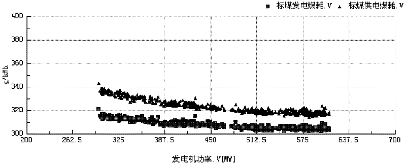
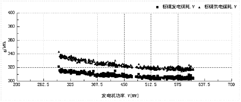
[0028] 2) taking one of the at least two indicators as the abscissa, and taking the rest of the at least two indicators as the ordinate, draw a graph;

[0029] 3) Using the graph, analyze the relationship between the different indicators and / or the relationship between the indicators and other conditions.

[0030] Wherein, in step 1), at least two indicators of th...


PUM


Abstract

The invention discloses an equipment state detecting method used for a thermal power plant, wherein the method comprises the following steps of: 1) obtaining at least two indexes of equipment of the thermal power plant under different conditions at the same time point; 2) describing a curve by using one of at least two indexes as a horizontal coordinate and using the other index of at least two indexes as a vertical coordinate; and 3) analyzing a relationship between different indexes and / or a relationship between the indexes and other conditions by using the curve. By using the method provided by the invention, the relationship between different indexes and / or the relationship between the indexes and other conditions can be directly obtained through a non-time domain curve diagram; and thereby, an equipment condition can be analyzed and judged more comprehensively and visually, which is convenient for comprehensively judging the whole state of the equipment.

Description

Contents of the invention [0001] The invention relates to an equipment state detection method used in a thermal power plant. Background technique [0002] During the control of the power generation process of the thermal power plant, through the automatic control system, the plant operator can obtain various indicators of the equipment in real time to detect the equipment. [0003] Whether it is a distributed control system or a real-time database system, these equipment status detection devices mainly acquire the underlying data and detect a single system through configuration modeling, and use the time and value of the index point as the horizontal and vertical coordinates , to get a time-based graph. Professional technicians can only obtain single-point indicators corresponding to time points through time-based graphs, but cannot obtain the relationship between different indicators, cannot detect equipment status information from multiple levels and angles, and cannot co...

Claims


Application Information

Patent Timeline
Patent Type & Authority Applications(China)
IPC IPC(8): G06Q10/00G06Q50/00G01D21/02
Inventor 孟炜何宁石朝夕王德军赵书君王曦钊杨春燕
Owner CHINA SHENHUA ENERGY CO LTD
Why Eureka
Try Eureka