Hydraulic valve assembly having a cartridge insert valve exhibiting a closing element arranged in a pressure equalized manner

A technology of hydraulic valves, closing bodies, applied in the direction of valve operation/release devices, valve devices, slide valves, etc.

Active Publication Date: 2012-01-04
PARKER HANNIFIN CORP
View PDF5 Cites 3 Cited by
  • Summary
  • Abstract
  • Description
  • Claims
  • Application Information

AI Technical Summary

Problems solved by technology

[0003] The known valve arrangement has the disadvantage that, due to the unavoidable tolerances in the manufacture of the bore in the valve block, different positions of the valve sleeve or its valve seat relative to the cover cover can occur, since the valve sleeve is placed in the assembly valve During operation, the closing element is pushed against the step part under the action of the control oil pressure, and the step part has different positions limited by the tolerance

Method used


Image

  • Hydraulic valve assembly having a cartridge insert valve exhibiting a closing element arranged in a pressure equalized manner
  • Hydraulic valve assembly having a cartridge insert valve exhibiting a closing element arranged in a pressure equalized manner
  • Hydraulic valve assembly having a cartridge insert valve exhibiting a closing element arranged in a pressure equalized manner

Examples


Embodiment Construction

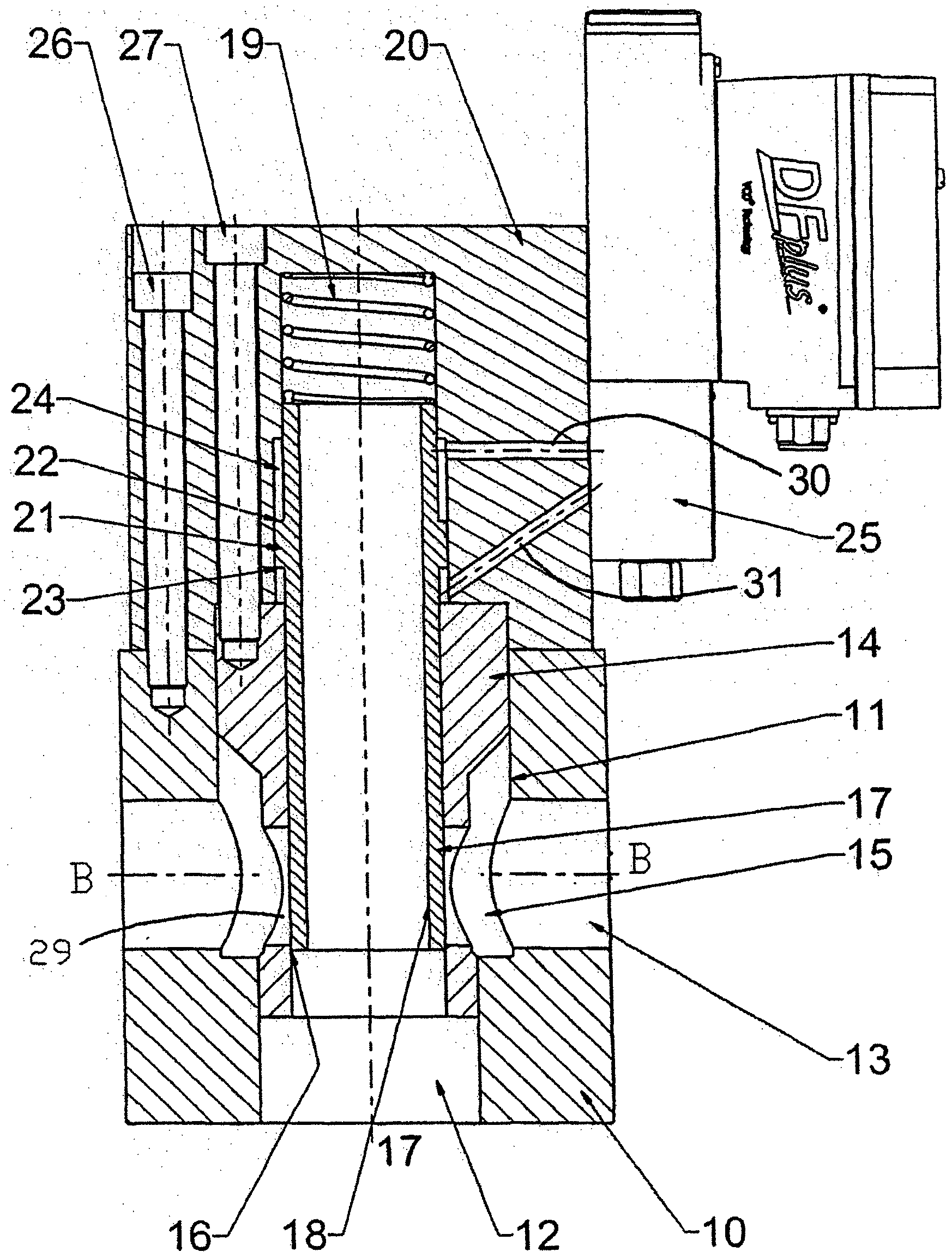
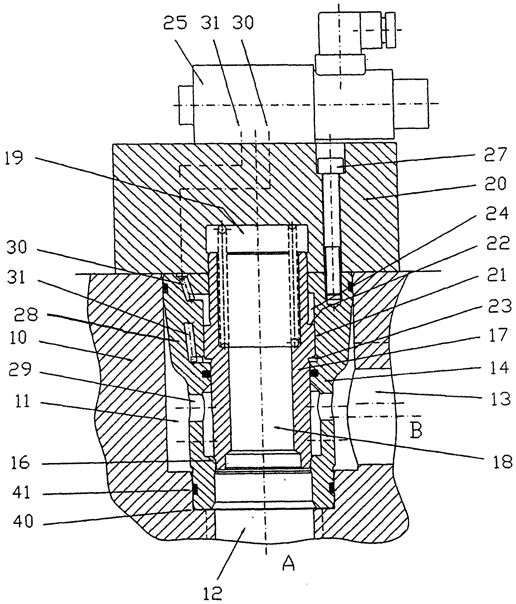
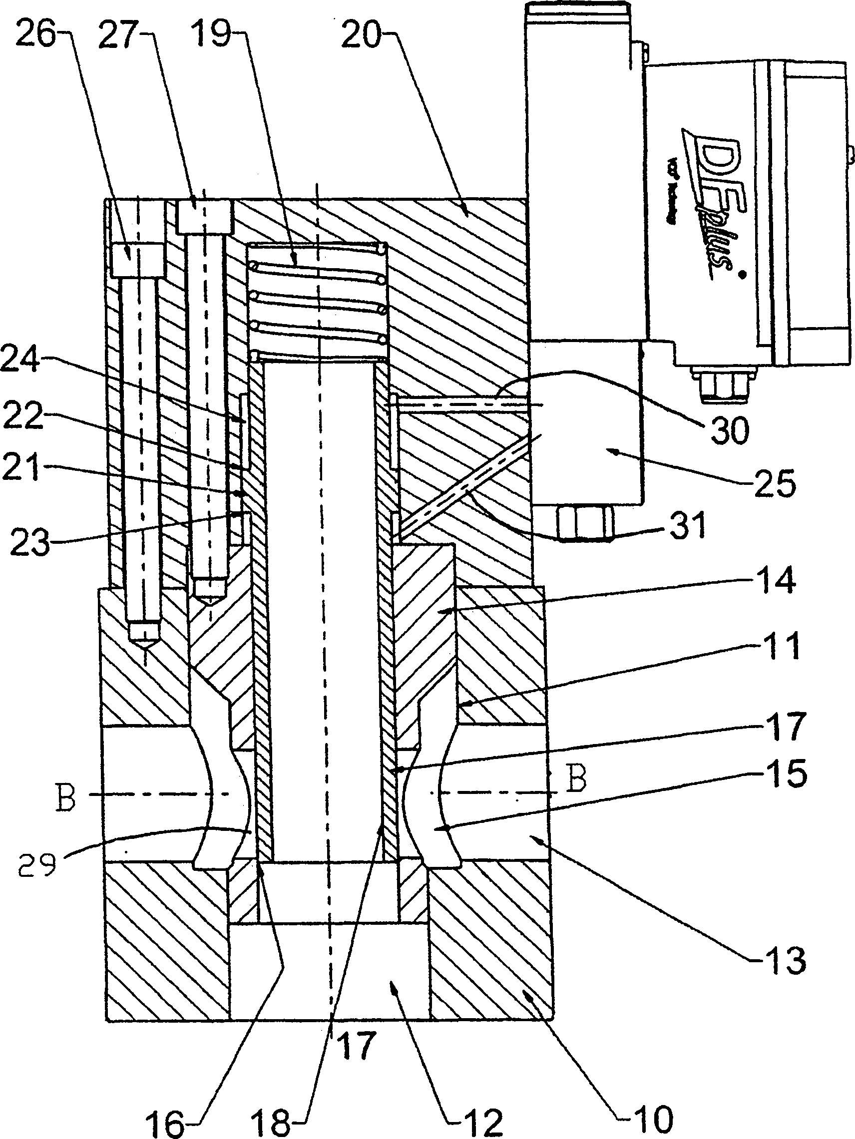
[0022] According to figure 1 In the illustrated embodiment, holes 11 are introduced in the valve block 10 for accommodating the assembly valves which are still to be described. Furthermore, a flow channel 12 (port A) and a flow channel 13 (port B) are arranged in the valve block 10 , which are each connected to the bore 11 in such a way that That is, the connection between the flow channels 12 and 13 can be closed or opened by a fitting valve inserted into the hole 11 . The bore 11 is closed by a valve cover cover 20 which is placed on the valve block 10 and is firmly screwed to the valve block 10 by means of bolts 26 .

[0023] The assembly valve inserted into the bore 11 of the valve block 10 comprises a valve sleeve 14 inserted into the bore 11 and in which the closing body 17 is movable. The valve sleeve 14 has a plurality of openings 29 in the region of the flow channel 13 (port B) leading away from the bore 11 for the hydraulic fluid introduced into the valve block 10 ...


PUM


Abstract

The invention relates to a hydraulic valve assembly having a cartridge insert valve in a bore hole designed in a valve block and connected to the flow channels arranged in the valve block, comprising a valve sleeve inserted in the bore hole and a closing member guided into said sleeve, wherein the valve sleeve forms a valve seat for the closing member in the closing position thereof and the closing member can be moved by means of a connected hydraulic pre-control between the closed position thereof seated on the valve seat and separating the flow channels from one another, and an opened position pushed into the valve sleeve, and the bore hole is sealed tight by the cartridge insert valve inserted therein via a valve cover connected to the valve block. The closing member forms a sleeve-shaped closing element (17) exhibiting a through-hole (18) and thus ring surfaces on both ends thereof, the surfaces having identical area, and a pressure equalization chamber (19) corresponding with thethrough-hole (18) of the closing element (17) is formed in the valve cover (20) such that the closing element (17) is engaged on both sides with the pressure enacting in the adjustment direction of the element, which is seated completely pressure-equalized in the valve sleeve (14), wherein a radially protruding collar (21) having control surfaces (22, 23) opposite one another in the adjustment direction is arranged on the outer circumference of the closing element (17) for adjustment thereof. The control surfaces can be loaded by the control oil conducted via the hydraulic pre-control (25) for moving the closing element (17) in the valve sleeve (14), and the valve sleeve (14) inserted in the bore hole (11) of the valve block is fastened on the valve cover (20), the valve seat (16) formed on the valve sleeve (14) thereby maintaining an unaltered distance from the valve cover (20) during operation of the valve assembly.

Description

technical field [0001] The invention relates to a hydraulic valve arrangement with an assembly valve which is inserted into a bore formed in a valve block and connected to a flow channel arranged in the valve block , comprising a valve sleeve inserted (einsetzen) into the bore and a closing element (Schlieβglied) guided in the valve sleeve, wherein the valve sleeve forms a valve seat for the closing element in its closed position, and The closing element can be moved between a closed position in which it rests on the valve seat and separates the flow passages from one another and an open position displaced in the valve sleeve by means of a coupled hydraulic pilot, and the hole and the plug inserted therein The assembly valve is sealed (verschlieβen) by a valve cover cap connected to the valve block. Background technique [0002] Such a valve arrangement is available from Parker Hannifin GmbH & Co. KG in the catalog "Industrial Hydraulic Valves" of the TDA series, catalog pa...

Claims


Application Information

Patent Timeline
Patent Type & Authority Applications(China)
IPC IPC(8): F16K3/26F16K31/124
CPCF16K31/124F16K3/265F16K3/246F16K3/26
Inventor D·邦格G·舍费尔
Owner PARKER HANNIFIN CORP
Why Eureka
Try Eureka