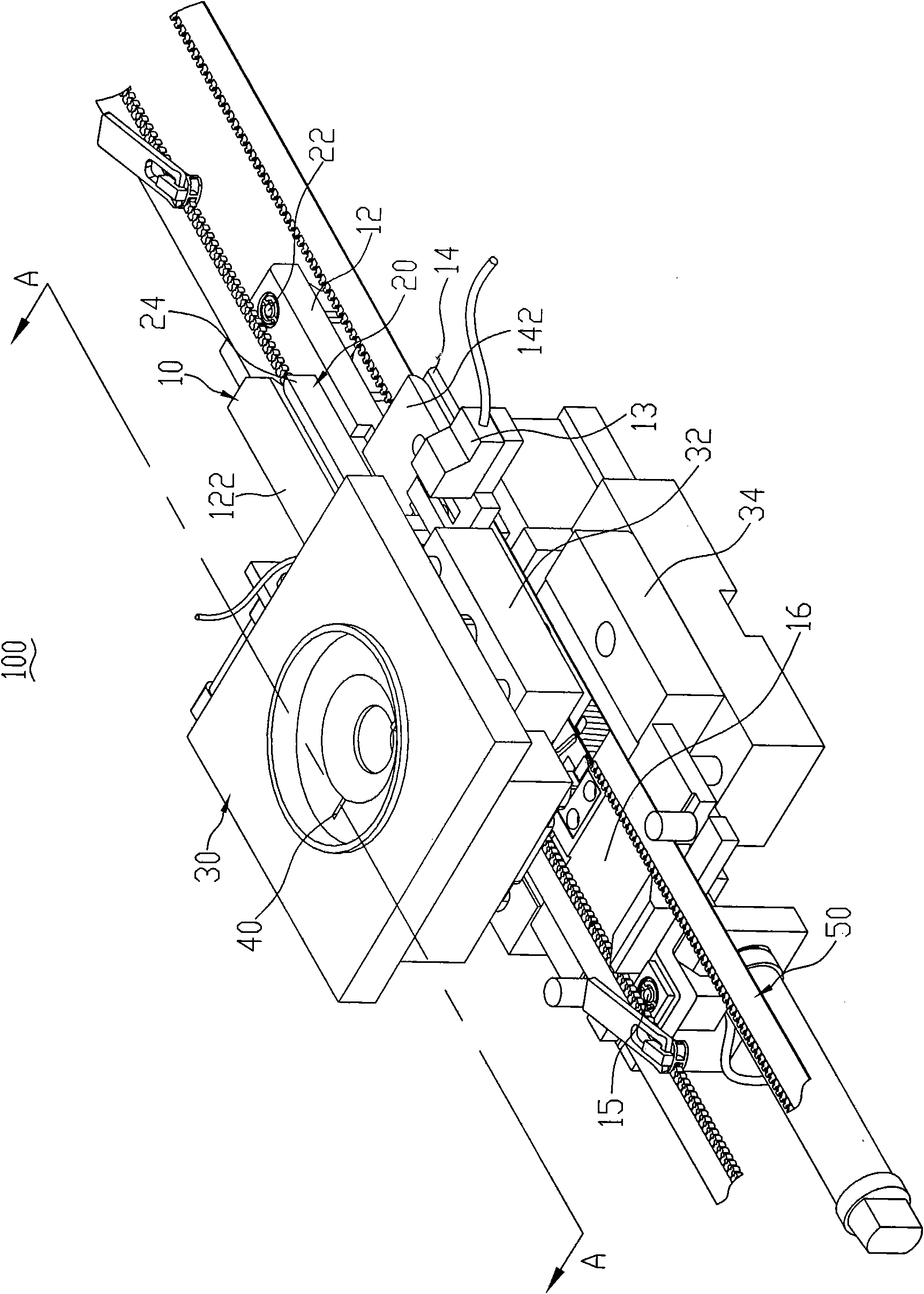
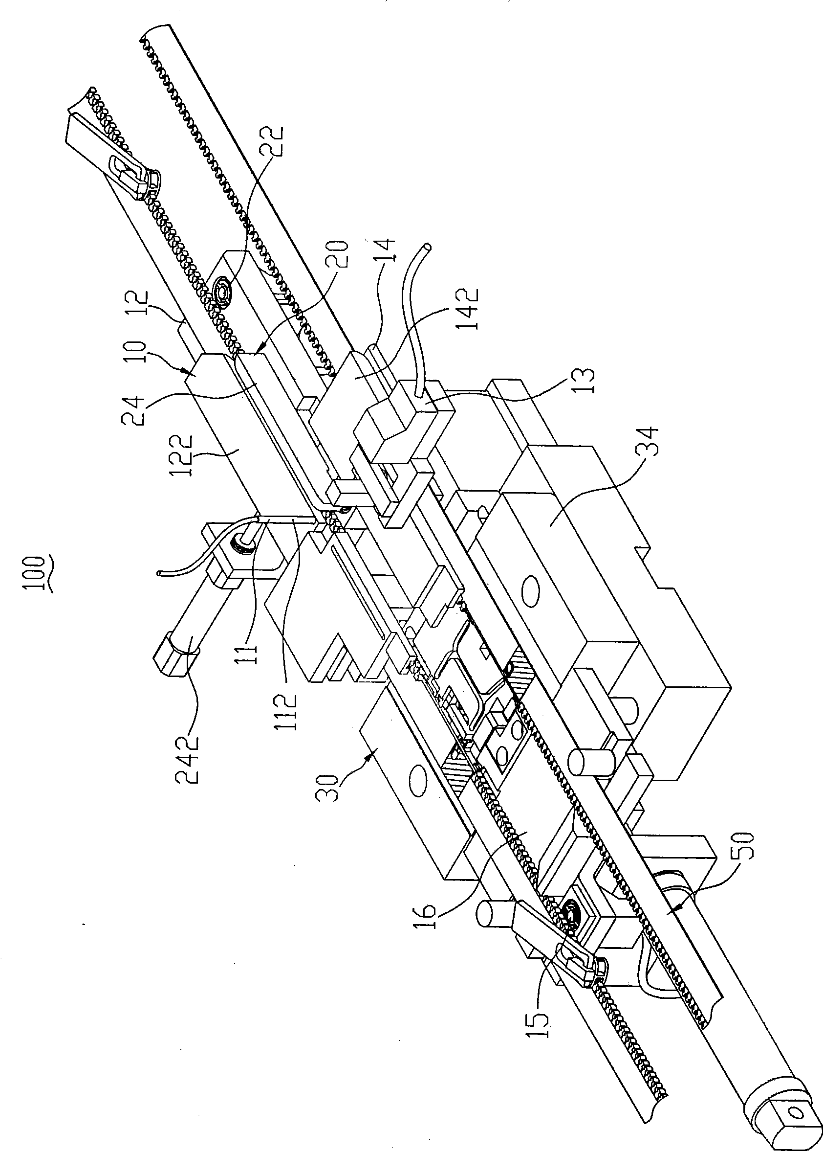
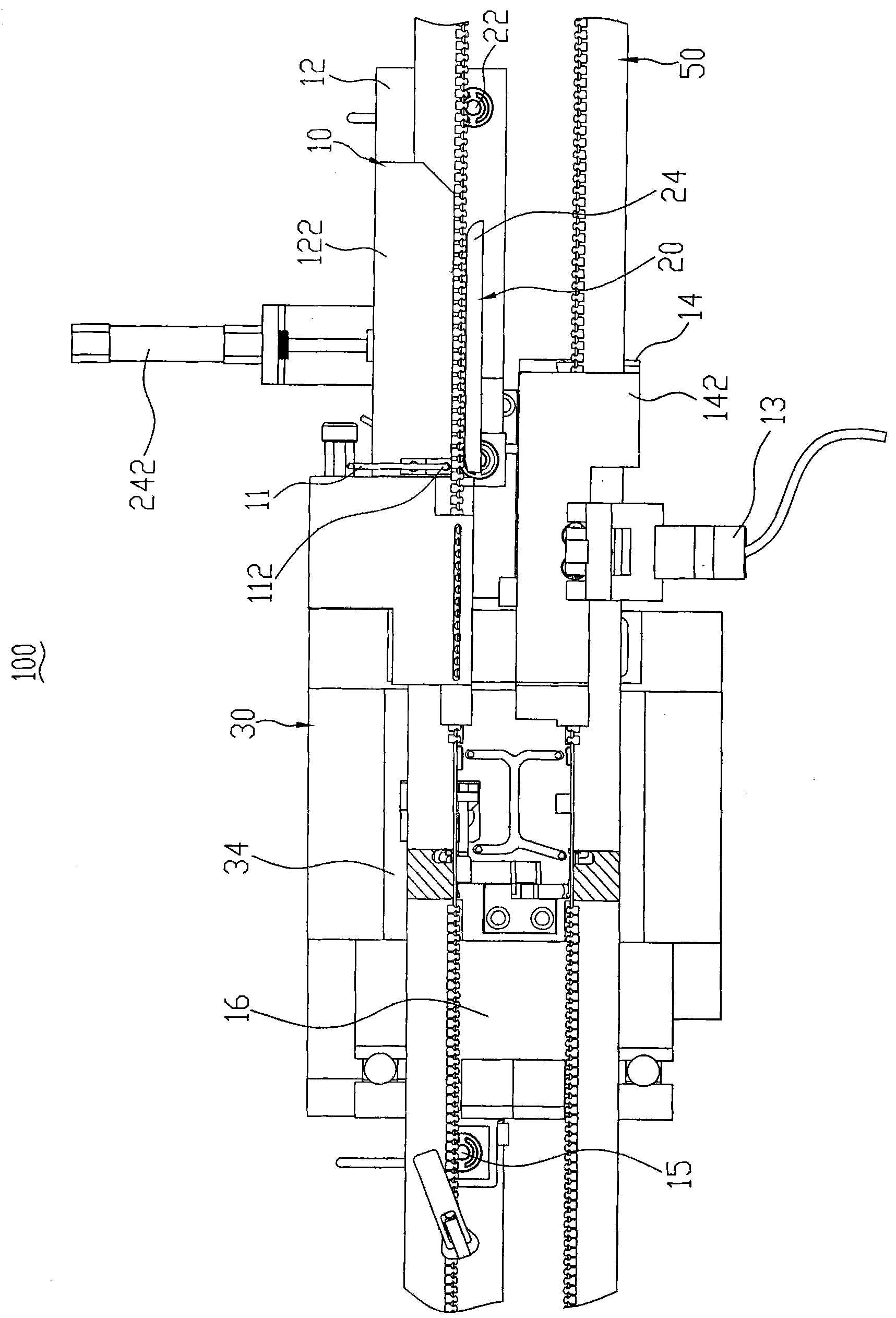
Zipper conveying and positioning mechanism and top and bottom stop forming device adopting same

The technology of positioning mechanism and zipper is applied in the fields of zipper conveying positioning mechanism and upper and lower stop forming devices, which can solve the problems of high production cost, complex structure, unstable operation of the upper stop injection positioning device, etc. wear effect

Active Publication Date: 2014-09-10
FUJIAN SBS ZIPPER SCI & TECH CO LTD
View PDF5 Cites 0 Cited by
  • Summary
  • Abstract
  • Description
  • Claims
  • Application Information

AI Technical Summary

Problems solved by technology

[0003] However, the micro switch of the detector needs to be in contact with the zipper chain for detection, and the micro switch will be in contact with the slider on the chain, which results in higher requirements for the detection sensitivity of the micro switch and structural more complex
Since the micro switch is constantly worn out, it requires constant adjustment and maintenance, resulting in unstable operation of the top stop injection positioning device and high production costs

Method used


Image

  • Zipper conveying and positioning mechanism and top and bottom stop forming device adopting same
  • Zipper conveying and positioning mechanism and top and bottom stop forming device adopting same
  • Zipper conveying and positioning mechanism and top and bottom stop forming device adopting same

Examples


Embodiment Construction

[0036] Please refer to Figure 9 , which is shown as a perspective view of the open zipper chain 50 to be processed in the present invention. There are several segments of chain teeth 56 , and the distances between each segment of chain teeth 56 are equal to each other to form a plurality of blank segments 58 . Each blank section 58 of the two chain belts 52, 54 is respectively provided with a punching hole 51 close to the bottom stop position, and the two punching holes 51 are respectively close to the cloth ribs 53 of the two chain belts 52, 54, and the cloth is not cut off. Tendon53. The upper and lower stops (not shown) of the long zipper chain 50 are respectively formed on the two ends of the blank section 58 . One end of the bottom stop (not shown) of the zipper chain 50 is adjacent to the fastener element 56 , and the other end extends into the punching hole 51 . Each chain element 56 of the left chain belt 52 is threaded with a slider 55 .

[0037] Please refer to ...


PUM


Abstract

The invention relates to a zipper conveying and positioning mechanism and a top and bottom stop forming device adopting the zipper conveying and positioning mechanism. The zipper conveying and positioning mechanism is used for conveying zipper long chains with assembled pulling heads and positioning the zipper long chains with assembled pulling heads when a forming mold works, each zipper long chain comprises a left chain belt and a right chain belt, punch holes are arranged on a blank section of each left chain belt, each pulling head is penetrated on each left chain belt, the zipper conveying and positioning mechanism is correspondingly provided with a traction mechanism at the left chain belts and the right chain belts and is characterized by also comprising a punch hole detector, the punch hole detector is connected with the traction mechanism through a time delay mechanism, and the punch hole detector is in arrangement correspondingly to the left chain belts and is used for detecting the punch holes. The zipper conveying and positioning mechanism and the top and bottom stop forming device adopting the zipper conveying and positioning mechanism have the advantages that the structure is simple, and the operation is stable.

Description

technical field [0001] The invention relates to a zipper conveying and positioning mechanism and an up and down stop forming device using the mechanism, in particular to a zipper conveying and positioning mechanism for injection molding up and down opening zipper long chains and an up and down stop forming device using the mechanism. Background technique [0002] Existing zippers can be roughly divided into open zippers and closed zippers. Because the two ends of the open zipper chain belt can be separated freely, the open zipper is widely used in fields such as clothing. The traditional production method of the open zipper is to form the top and bottom stops first, and then insert the slider into the chain belt from the top stop, which may cause the slider to come out from the top stop. For this reason, someone has specially designed a kind of molding device that can be inserted into the chain belt earlier by the slider, and then injection-molded the upper and lower stops, ...

Claims


Application Information

Patent Timeline
Patent Type & Authority Patents(China)
IPC IPC(8): B29C45/17B29C45/76B29L5/00
Inventor 王喆洪建源黄长辉
Owner FUJIAN SBS ZIPPER SCI & TECH CO LTD
Why Eureka
Try Eureka