Mouse button locking device

A locking device and button technology, applied in the field of mouse, to reduce the difficulty of design

Inactive Publication Date: 2012-01-11
APEXONE MICROELECTRONICS SHANGHAI +1
View PDF8 Cites 1 Cited by
  • Summary
  • Abstract
  • Description
  • Claims
  • Application Information

AI Technical Summary

Problems solved by technology

[0004] The purpose of the present invention is to provide a mouse button locking device to

Method used


Image

  • Mouse button locking device
  • Mouse button locking device
  • Mouse button locking device

Examples


Embodiment Construction

[0037] The specific implementation of the present invention will be described below in conjunction with the accompanying drawings, and the following description is based on the detection of mouse buttons as an example. Those skilled in the art can fully understand that the technical solution of the present invention can also be completely applied to other electronic devices. Key detection on.

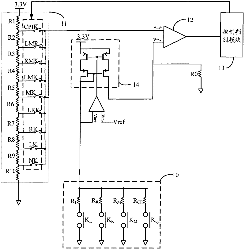
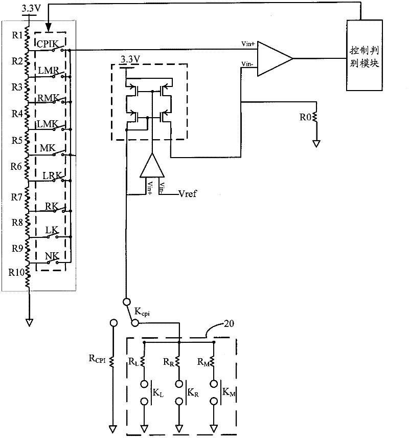
[0038] Please refer to figure 2 As shown, it is an overall circuit diagram for implementing the mouse button locking device of the present invention, wherein the mouse button locking device includes a first button resistor module 20, a CPI button resistor R CPI , CPI key switch K CPI And the mouse controller, the composition and function of each module will be described in detail below.

[0039] The first button resistor module 20 includes a plurality of parallel button switches and button resistors that cooperate with the button switches. In the present embodiment, three buttons are...


PUM


Abstract

The invention provides a mouse button locking device, A CPI (count per inch) button resistor is connected with a CPI button switch selectively. When a user adjusts the CPI value of a mouse, only the CPI resistor is in a connection state, so that the erroneous judgment of a mouse controller caused by pressing other buttons down simultaneously can be prevented, the CPI resistor can be simultaneously prevented from being in parallel connection with other button resistors, and the situation does not need to be considered in the setting in a mouse control chip, thereby being favorable for reducing the design difficulty of the mouse control chip.

Description

technical field [0001] The invention relates to a mouse, in particular to a device for controlling the buttons of the mouse. Background technique [0002] The mouse is a relatively common input device for computer devices. In order to cope with different functions in the operating system, the mouse is usually provided with a left button, a right button and a middle button. In addition, for some high-end application environments (such as games or precision drawing, etc.), the mouse needs to have a higher resolution, that is, CPI (measurements per inch, countper inch). The CPI of the optical mouse currently on the market is 400, which means that every inch of movement will return 400 coordinates. With the development of technology, the performance of the mouse is getting better and better, and now the CPI value of some mice exceeds 2000, which is very suitable for large-resolution screen operation. This shows that different CPI values ​​are required for different application...

Claims


Application Information

Patent Timeline
IPC IPC(8): G06F3/033
Inventor 熊大鹏谢东海谢小兵李云涛
Owner APEXONE MICROELECTRONICS SHANGHAI
Why Eureka
Try Eureka