Electronic part supplying device
A technology for electronic component supply and electronic component installation, applied in the direction of electrical components, electrical components, etc., can solve problems such as instability, standing up in the storage room, irregular posture, and deterioration of component mounting accuracy
- Summary
- Abstract
- Description
- Claims
- Application Information
AI Technical Summary
Problems solved by technology
Method used
Image
Examples
no. 1 Embodiment approach
[0034] Embodiments of the electronic component supply device according to the present invention will be described.
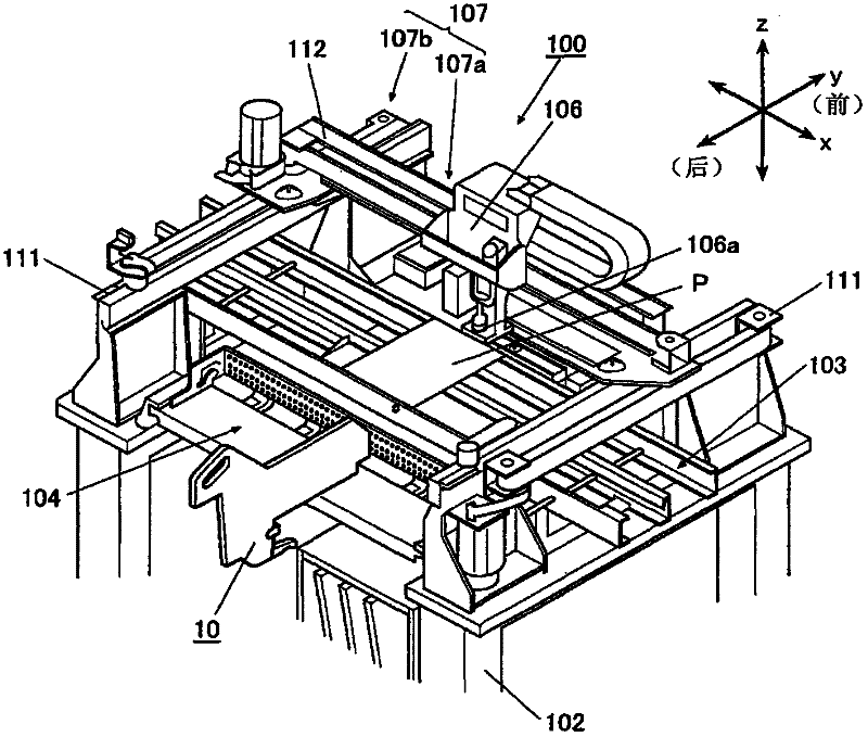
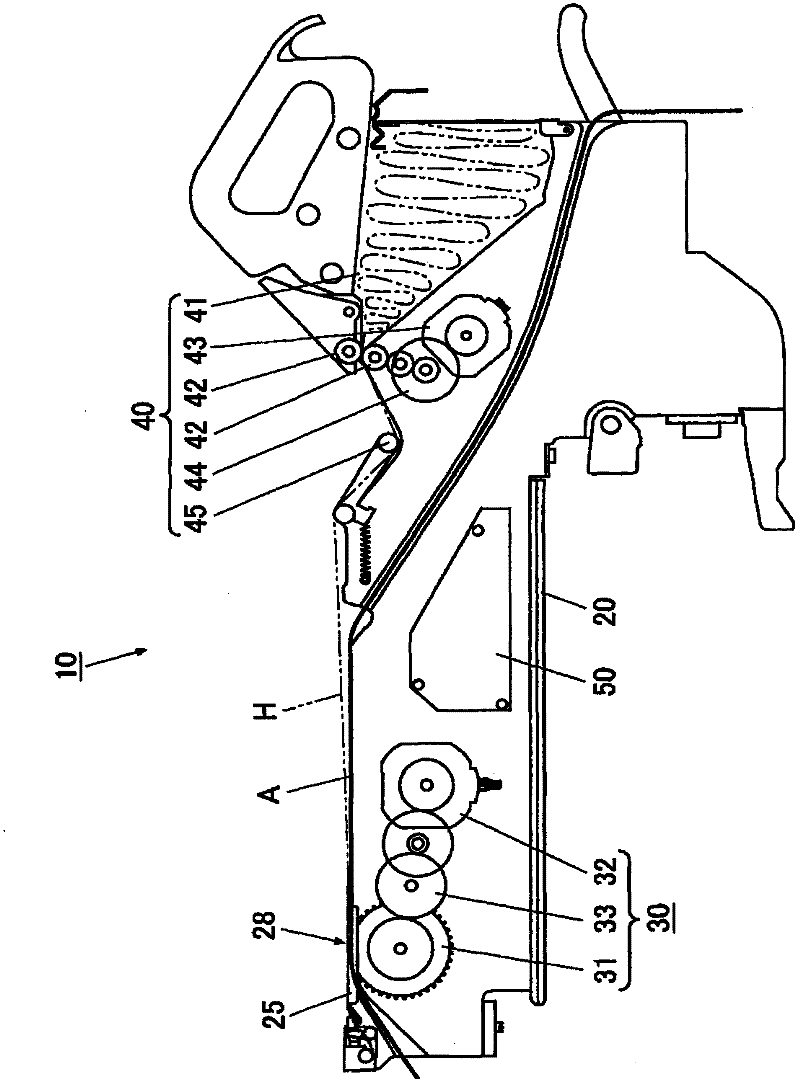
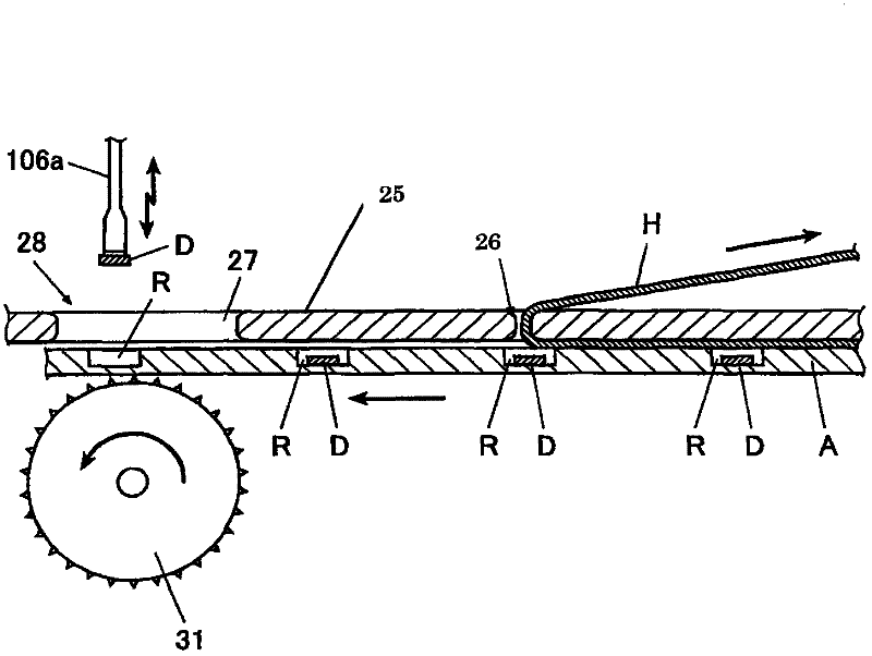
[0035] The electronic component feeder 10, which is an electronic component supply device, is detachably mounted on the electronic component mounting device 100, and transports the carrier tape A in which electronic components are sealed at uniform intervals by using the outer packaging tape H. The electronic component is supplied to the electronic component mounting apparatus 100 by suction at a predetermined supply position on the route by the mounting head 106 of the electronic component mounting apparatus 100 .
[0036] Here, in the electronic component mounting apparatus 100, the horizontal direction in which the substrate P is transported from the previous process to the subsequent process is defined as the X-axis direction, and the horizontal direction perpendicular thereto, that is, along the direction of The longitudinal direction of the feeder 10 is re...
no. 2 Embodiment approach
[0099] In the above-mentioned electronic component feeder 10, the reduction of the peeling speed of the outer cover tape H in the storage room R is realized by the arrangement of the peeling part 26 relative to the supply part 28, but by changing the speed pattern of the feeder motor 32, it is also possible to obtain same effect.
[0100] Figure 5 (A) shows an example of changing the speed pattern of the feeder motor 32, Figure 5 (B) shows the positional relationship in the stopped state of the carrier tape A corresponding to the speed pattern.
[0101] As shown in the figure, even if the disposition of the peeling part 26 relative to the supply part 28 is not an integral multiple of the intermittent feeding amount once, for example, by adjusting the acceleration in the rising section V1 and the deceleration in the falling section V3 in the speed mode , and the section length of the highest speed section V2, the feeder 32 may be controlled so that the storage chamber R pas...
no. 3 Embodiment approach
[0104] In addition, in the above-mentioned electronic component feeder 10, by optimizing the formation position of the peeling part 26 at the upper cover 25, the reduction of the peeling speed of the outer cover tape H in the storage room R is realized, but it is not limited to this, and may be The same effects can be obtained by changing the setting position of the supply unit 28 .
[0105] Figure 6 (A) A graph showing the same velocity pattern as above, Figure 6 (B) is an explanatory diagram showing the arrangement of the supply part 28 and the peeling part 26 in the above-mentioned conventional top cover, Figure 6 (C) shows the 3rd embodiment of this invention which realized the reduction of the peeling speed of the cover tape H of the storage room R by changing the arrangement|positioning of the supply part 28. FIG.
[0106] As described above, if the supply portion 28 falls within the range of the opening 27 in the upper cover 25 , it can be changed by changing the s...
PUM
 Abstract
Description
Claims
Application Information
 - R&D
- Intellectual Property
- Life Sciences
- Materials
- Tech Scout
- Unparalleled Data Quality
- Higher Quality Content
- 60% Fewer Hallucinations
Browse by: Latest US Patents, China's latest patents, Technical Efficacy Thesaurus, Application Domain, Technology Topic, Popular Technical Reports.
© 2025 PatSnap. All rights reserved.Legal|Privacy policy|Modern Slavery Act Transparency Statement|Sitemap|About US| Contact US: help@patsnap.com


