Horizontal well landing geosteering method

A horizontal well and geosteering technology, applied in directional drilling, earthmoving, wellbore/well components, etc., can solve the problems of poor seismic data quality, low well control degree, large structural interpretation error, etc., and achieve calibration design Structural error, ensuring the success rate of drilling, the effect of ensuring the success rate of drilling

Inactive Publication Date: 2012-01-18
PETROCHINA CO LTD +1
View PDF3 Cites 20 Cited by
  • Summary
  • Abstract
  • Description
  • Claims
  • Application Information

AI Technical Summary

Problems solved by technology

However, due to the low degree of well control in the drilling block, the lack of data, and the complex geological conditions, the lateral variation of the formation thickness is large, resulting in a large error in predicting the vertical depth of the landing; at the same time, affected by the ground environment and geological conditions, the seismic data quality is poor, resulting in The structural interpretation error is large, and the landing accuracy cannot be guaranteed

Method used


Image

  • Horizontal well landing geosteering method
  • Horizontal well landing geosteering method
  • Horizontal well landing geosteering method

Examples


Embodiment 1

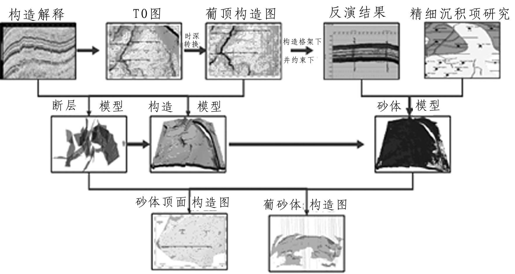
[0037] Example 1. Well N243-P297, the design target layer is PI4-3 layer, and the structural sand body model of the target area is established. The vertical depth of the landing point of the target layer is estimated to be 1272.84m, see Figure 4 .

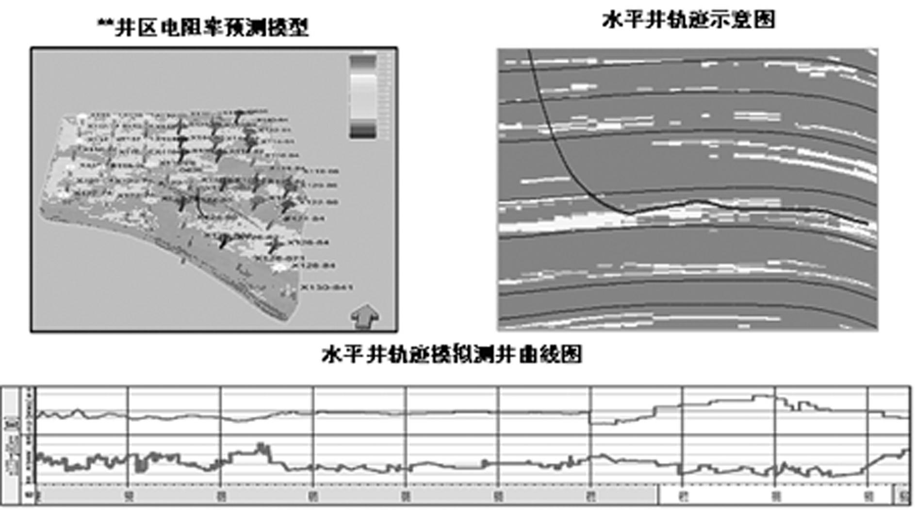
[0038] Based on the establishment of the structural sand body model, combined with the electrical logging curves of the surrounding wells, the electrical influence model of the target area is established to realize the purpose of real-time simulation of the logging curves with any trajectory, see figure 2 .

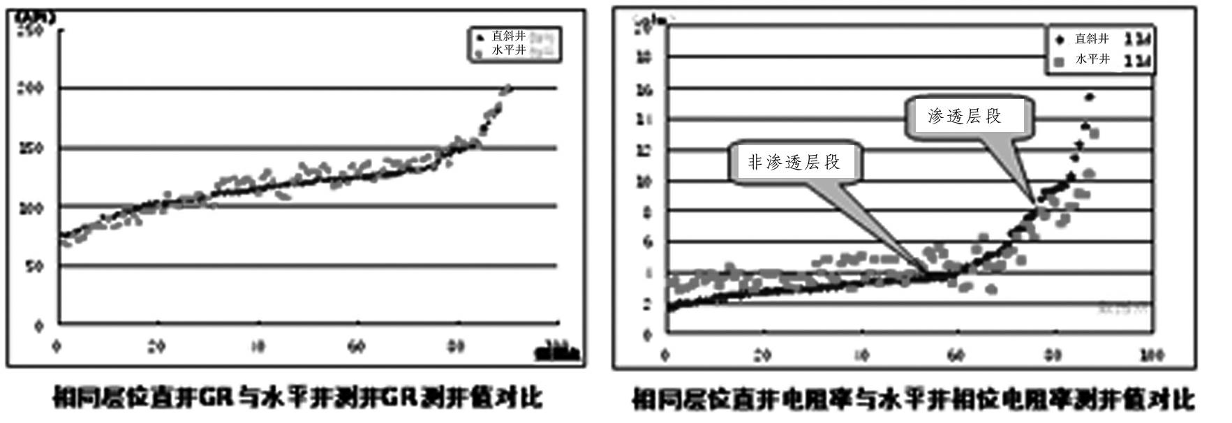
[0039] During the landing process, the real drilling curve data will be corrected by software first. Adding it to the landing comparison model, comparing the shape difference between the horizontal well curve and the vertical well curve, can accurately identify the currently drilled layer. Compare sections one by one to judge structural changes, determine the true vertical depth of the landing point, and design the most re...

Embodiment 2

[0043] Example 2: Well N266-P251, the design target layer is PI1-2 layer, and the vertical depth of the target layer at the expected landing point is 1260.62m.

[0044] When drilling to mark point 6, according to the calculation of Well N266-250, the current vertical depth should be 1252.5m (actually drilled 1247.5m), which is 5.0m shallower than the design. According to the calculation of Well N266-252, the current vertical depth should be 1253.1m (actual Drilling 1247.5m), 5.6m shallower than the design ( Figure 9 ). It is considered that the wellbore trajectory needs to be adjusted in time to prevent layer penetration.

[0045] After section-by-section comparison, it was finally determined that the actual drilling target layer was 5.6m ahead of the design ( Figure 10 ), redesign the well trajectory, increase the inclination at a large angle, and finally land smoothly. The drilling rate of this well was 94.1%.


PUM


Abstract

The invention relates to a novel thin-interbedded horizontal well landing geosteering method. The horizontal well landing geosteering method includes the following steps: (1) constructing a horizontal well landing geosteering comparison model; (2) vertically correcting an LWD (Logging While Drilling) curve of a curve section; (3) carrying out error judgement and determining structure errors in real time by means of the fine comparison of the landing geosteering comparison model; and (4) determining a trajectory adjustment according to the structure errors scheme. The method realizes the transformation from conventional mark comparison to digitalized continuous comparison, and has the dual characteristics of real-timeliness and accuracy; and the digitized comparison profile of a landing section is established before drilling, the LWD curve is digitized in real time in the process of landing, and is finely compared with the profile after the vertical depth is corrected, the structure is corrected in real time, a result is judged according to the structure errors, the trajectory design is updated in real time, and thereby accurate landing can be realized.

Description

technical field [0001] The invention belongs to the field of oil field drilling, and in particular relates to a landing and guiding method for a horizontal well. Background technique [0002] In recent years, in order to improve the development efficiency of "three low" oilfields, the application of horizontal wells has been continuously increased to achieve high efficiency with fewer wells. However, due to the low degree of well control in the drilling block, the lack of data, and the complex geological conditions, the lateral variation of the formation thickness is large, resulting in a large error in predicting the vertical depth of the landing; at the same time, affected by the ground environment and geological conditions, the seismic data quality is poor, resulting in The structural interpretation error is large, and the landing accuracy cannot be guaranteed. Contents of the invention [0003] In order to solve the deficiencies in the background technology, the prese...

Claims


Application Information

Patent Timeline
Patent Type & Authority Applications(China)
IPC IPC(8): E21B47/022E21B7/04
Inventor 郭殿军赵玉武么忠文王瑞管西永
Owner PETROCHINA CO LTD
Why Eureka
Try Eureka