Droplet discharging head

a technology of droplets and nozzles, which is applied in printing and other directions, can solve the problems of inability to achieve high-quality image recording, deterioration of the landing position of ink droplets discharged from the nozzle, and prone to warping in the longitudinal direction, so as to increase the strength of droplets, increase the strength with respect to bending in the longitudinal direction thereof, and increase the effect of droplet strength

Inactive Publication Date: 2005-03-24
FUJIFILM CORP
View PDF5 Cites 5 Cited by
  • Summary
  • Abstract
  • Description
  • Claims
  • Application Information

AI Technical Summary

Benefits of technology

[0021] According to the present invention, the rigid members for reinforcing strength can be used for a variety of applications, and not simply for increasing the strength of the droplet discharging head in the longitudinal direction, and hence reinforcement of the strength can be ensured, without increasing the number of components.
[0022] As described above, according to the droplet discharging head relating to the droplet discharging head, in a full line type droplet discharging head of long dimension, the strength with respect to bending in the longitudinal direction thereof is increased, and hence warping in the longitudinal direction due to internal stress caused by processing, bonding, or the like, of the structure of thin plates during manufacture, can be prevented, thereby making it possible to guarantee the flatness of the discharge ports, increase the accuracy of the landing positions of the discharged droplets, and hence achieve image recording of high quality.

Problems solved by technology

In an inkjet head of this kind formed by a laminated structure of thin plates, if the head has a long dimension, then it is liable to warping in the longitudinal direction, due to internal stress produced by the bonding and heating processes during manufacture.
If warping occurs in the inkjet head, then problems occur, for example, the accuracy of the landing positions of the ink droplets discharged from the nozzles deteriorates, and image recording of high quality cannot be achieved, and therefore various methods for preventing warping of this kind have been proposed.
However, in the technology described in Japanese Patent Application Publication No. 7-164636, even if the difference of the coefficient of thermal expansion is less than 100 ppm, some stress will be generated, and if the head has a long dimension, it will have insufficient strength, and a problem arises in that phenomena, such as warping, curling, and the like, will occur due to the stress generated.
However, in the technology described in Japanese Patent Application Publication No. 9-277534, the strength of the head is dependent on the strength of the supporting body and the ceiling plate, and since the base bodies are divided, there is liable to be insufficient strength at the connections between the respective base bodies, and warping, and the like, will be generated if the head is formed to have a relatively long dimension.
Moreover, in the technology described in Japanese Patent Application Publication No. 2002-67330, pressure is applied by means of screw fastenings, but a problem arises in that the stress is liable to concentrate in the region of the screws, and hence there is a risk of other damage occurring.
However, in the technology disclosed in Japanese Patent Application Publication No. 2002-210976, since a resin section forming an ink passage and ink discharge ports, and a thermal deformation suppressing member, which is a structural element for reinforcing the strength of same, are formed together in an integral manner, the material is limited to being resin, which does not necessarily have sufficient strength.

Method used


Image

  • Droplet discharging head
  • Droplet discharging head
  • Droplet discharging head

Examples


Embodiment Construction

[0036] Below, the droplet discharging head relating to the present invention is described in detail with reference to the accompanying drawings.

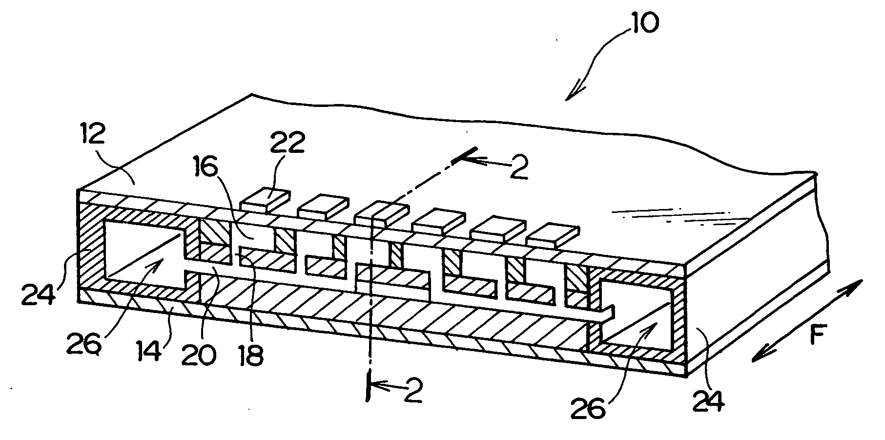
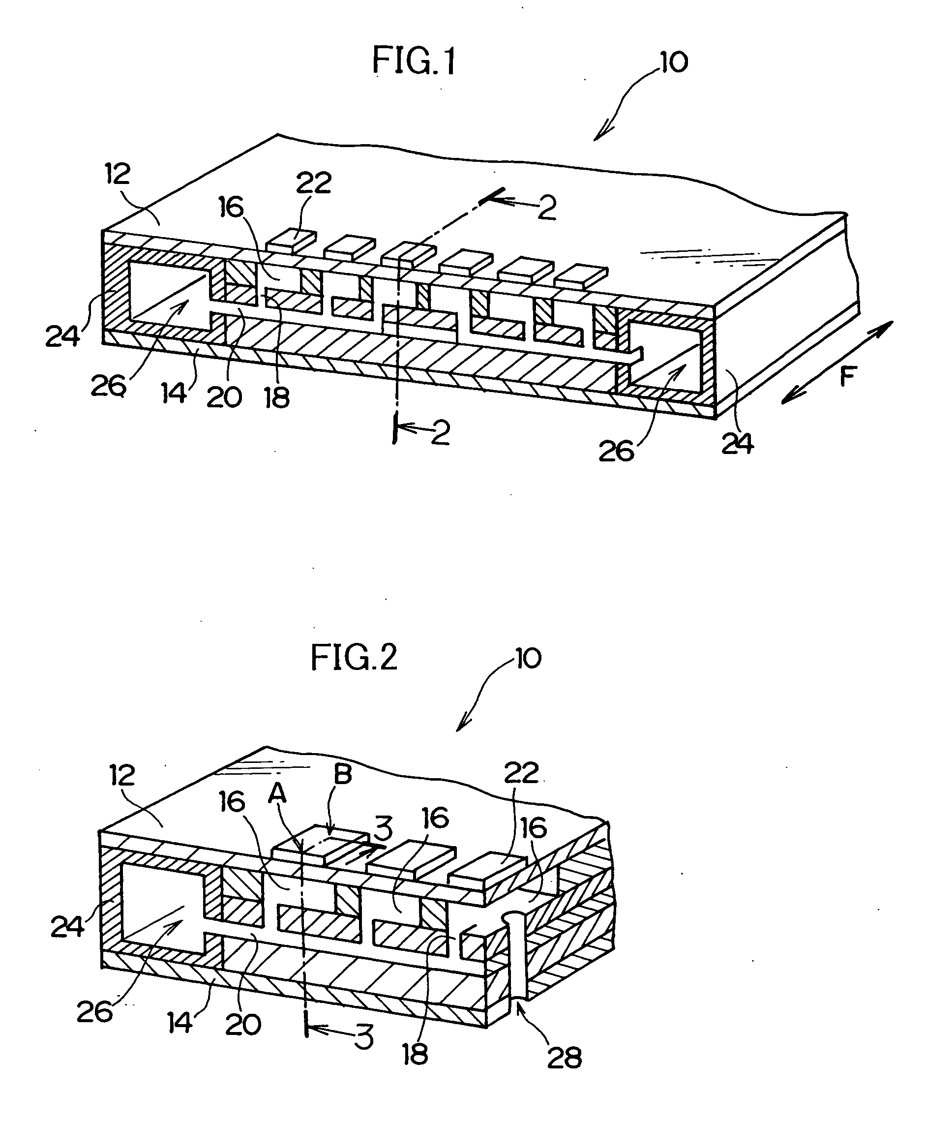
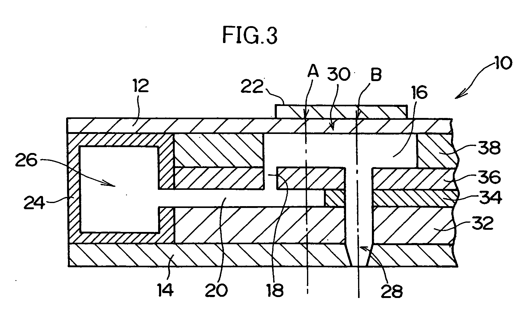
[0037]FIG. 1 is an approximate oblique view comprising a partial cross-sectional view showing an approximate illustration of one embodiment of a droplet discharging head according to the present invention. In the droplet discharging head according to the present embodiment, a piezoelectric type droplet discharging head which discharges liquid droplets by pressurizing a liquid by changing the volume of a pressure chamber filled with a liquid by means of a deforming action of a piezoelectric element, is applied to an inkjet head, but the present invention is not limited to an inkjet head of this kind.

[0038] As shown in FIG. 1, the droplet discharging head 10 according to the embodiment of the present invention (hereinafter, called the “inkjet head 10”) is constituted by a plurality of thin plates laminated between a ceiling plate 12 and a no...


PUM


Abstract

In the full line type droplet discharging head, discharge ports for discharging a liquid supplied by a liquid passage formed by laminating thin plates, as liquid droplets, are arranged in a line direction along a length corresponding to a full width of a recording medium; and a simple rigid member having higher rigidity than that of a structure constituted by laminating the thin plates is provided extending along the line direction.

Description

BACKGROUND OF THE INVENTION [0001] 1. Field of the Invention [0002] The present invention relates to a droplet discharging head, and more particularly, to a droplet discharging head in a recording head such as a full line type inkjet head, formed to have a long dimension by laminating together thin plates, whereby warping in the longitudinal direction due to internal stress caused by bonding, heat, or the like, is suppressed. [0003] 2. Description of the Related Art [0004] Image recording is known which uses a so-called inkjet method, wherein an image is recorded by discharging and propelling ink (ink droplets) from the nozzles of a recording head to deposit the ink onto recording paper, or the like. There are various ink discharge methods for recording heads (inkjet heads) based on an inkjet method. For example, known methods include: a piezoelectric method wherein the volume of a pressure chamber is caused to change by means of deformation of piezoelectric ceramics, ink is introdu...

Claims


Application Information

Patent Timeline
Patent Type & Authority Applications(United States)
IPC IPC(8): B41J2/14
CPCB41J2/14233B41J2002/14306B41J2002/14491B41J2002/14459B41J2002/14419
Inventor ENOMOTO, KATSUMIKOJIMA, TOSHIYA
Owner FUJIFILM CORP
Why Eureka
Try Eureka