Liquid ejection head and liquid ejection apparatus

a liquid ejection and liquid curtain technology, applied in printing and other directions, can solve the problems of poor landing precision, increased production costs, and increased production costs, so as to improve the reliability of the head and raise the landing precision of used droplets. , the effect of improving the accuracy of the landing

Inactive Publication Date: 2013-04-18
CANON KK
View PDF4 Cites 5 Cited by
  • Summary
  • Abstract
  • Description
  • Claims
  • Application Information

AI Technical Summary

Benefits of technology

[0007]Also, with the method illustrated in Patent Literature 1, since print droplets also pass through the liquid curtain, there is a risk that print droplets will be susceptible to the effects of the liquid curtain and have their landing positions altered. Also, with the method illustrated in Patent Literature 2, separate droplets are made to fly and land in a gutter in order to capture non-print droplets, but there is a risk that splash mist will occur during landing and contaminate the flight path.
[0008]One object of the present invention is to provide a liquid ejection head able to raise the landing precision of used droplets (print droplets) while also suppressing the creation of mist along the droplet flight path, and in addition, to provide a liquid ejection apparatus provided with the liquid ejection head.
[0009]A liquid ejection head of the present invention includes a first nozzle that continuously ejects droplets and collecting mechanism configured to collect unused droplets which are not used from among the droplets continuously ejected from the first nozzle. The collecting mechanism includes a second nozzle able to project a liquid surface positioned along the trajectory in which droplets ejected from the first nozzle fly, and a liquid surface driving mechanism that collects unused droplets ejected from the first nozzle by causing a liquid surface to be projected from the second nozzle, causing the unused droplets to collide and unite with the projected liquid surface, and causing the projected liquid surface to retreat.
[0010]According to the present invention, it is possible to raise the landing precision of used droplets (print droplets), since it is possible to sort and collect unused droplets (non-print droplets) without influencing the used droplets (print droplets). Also, since the liquid surface projected from the second nozzle for sorting does not form flying droplets, the creation of mist along the droplet flight path can be suppressed, and head reliability can be improved.

Problems solved by technology

Meanwhile, if a print droplet is charged, it will be susceptible to electrostatic interaction with preceding and successive charged droplets and charged mist adhering to the wall surface.
This is a problem because the droplet's flight trajectory will alter and landing precision will worsen.
Also, with the method illustrated in Patent Literature 1, since print droplets also pass through the liquid curtain, there is a risk that print droplets will be susceptible to the effects of the liquid curtain and have their landing positions altered.
Also, with the method illustrated in Patent Literature 2, separate droplets are made to fly and land in a gutter in order to capture non-print droplets, but there is a risk that splash mist will occur during landing and contaminate the flight path.

Method used


Image

  • Liquid ejection head and liquid ejection apparatus
  • Liquid ejection head and liquid ejection apparatus
  • Liquid ejection head and liquid ejection apparatus

Examples


first embodiment

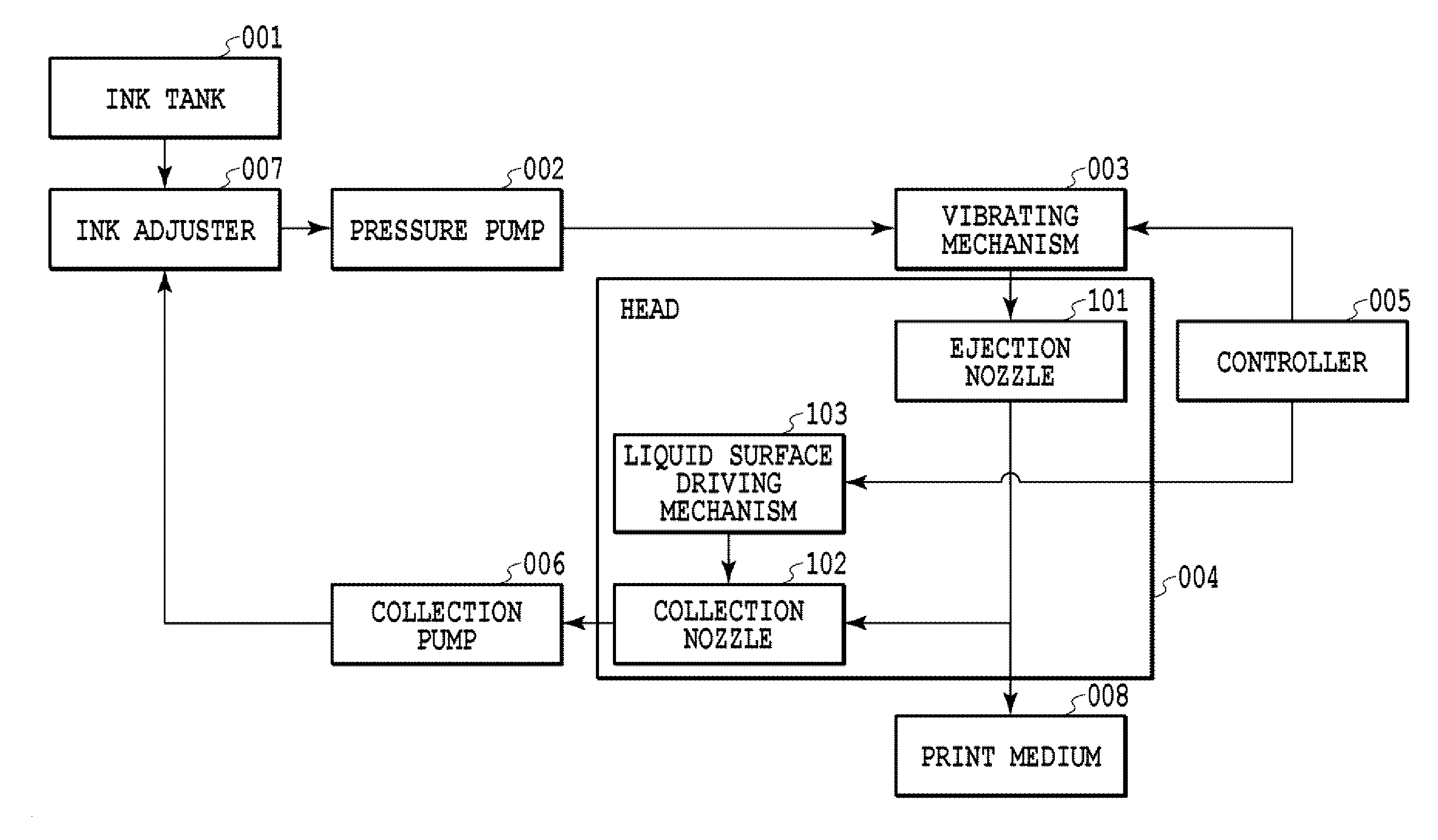
[0057]FIG. 1 is a schematic system diagram of a liquid ejection apparatus equipped with a liquid ejection head in accordance with a first embodiment of the present invention. A liquid ejection apparatus of the present invention is made up of an ink tank 001, a pressure pump 002, a vibrating mechanism 003, a head 004, a controller 005, a collection pump 006, and an ink adjuster 007. FIGS. 2 and 3 are an exploded perspective view and a cross-section of the head 004. As illustrated in FIG. 1, the head 004 includes ejection nozzles 101 (first nozzles), collection nozzles 102 (second nozzles), and liquid surface driving mechanisms 103.

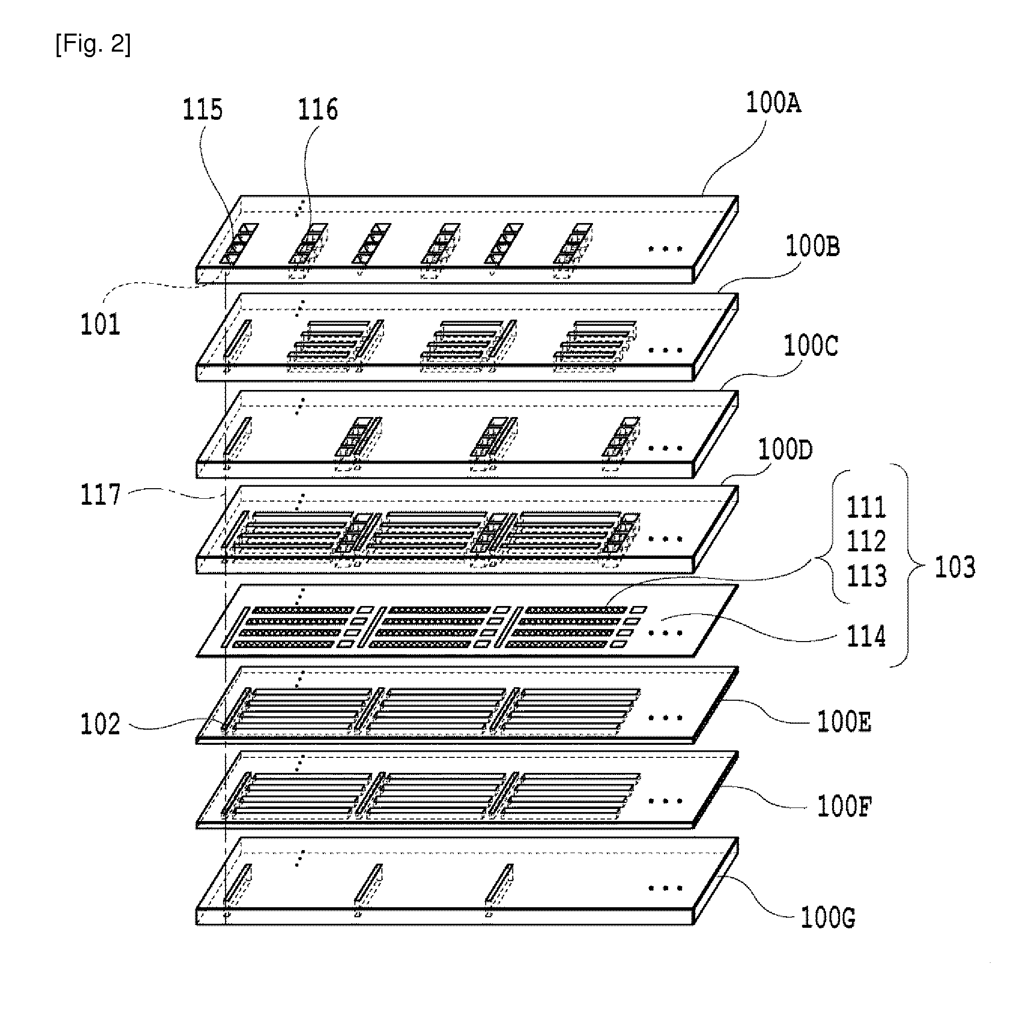
[0058]As illustrated in FIGS. 2 and 3, the head 004 has a layered configuration of planar members 100A to 100D, a vibrating plate 114, and planar member 100E to 100G, in that order. On these are formed the ejection nozzles 101, the collection nozzles 102, and the liquid surface driving mechanisms 103. Silicon, stainless steel, resinous materials, etc. may b...

second embodiment

[0083]Next, a second embodiment of the present invention will be explained. A schematic system diagram of a liquid ejection apparatus of the present embodiment is similar to the first embodiment. FIG. 12 is a cross-section of a liquid ejection head in accordance with the present embodiment. FIG. 13A is a plan view of respective component members of the head. FIG. 13B illustrates respective component members of a collection channel unit. In the present embodiment, a two-dimensional multi-nozzle head configuration is indicated, with nozzle lines formed in the Y direction and respective nozzle lines arranged along the X direction.

[0084]As illustrated in FIG. 12, a liquid surface driving mechanism 103A is provided adjacent to a collection channel 116 that communicates with a collection nozzle 102, and it is possible to project a liquid surface of liquid inside the collection nozzle 102 out from the tip aperture of the collection nozzle 102. A liquid surface projecting from a collection ...

third embodiment

[0124]Hereinafter, a third embodiment of the present invention will be explained with reference to the drawings. A system schematic of a liquid ejection apparatus of the present embodiment is similar to the first embodiment. FIG. 24 is an exploded perspective view of a liquid ejection head in accordance with the present embodiment. FIGS. 25A and 25B are cross-sections of the liquid ejection head in FIG. 24. Similarly to the above embodiments, the liquid ejection head is provided with ejection nozzles 101, supply channels 115, a vibrating mechanism 003, collection nozzles 102, and a liquid surface driving mechanism 103C. As illustrated in FIG. 25A, the vibrating mechanism 003 is disposed along a channel farther upstream than an ejection nozzle 101. In the present embodiment for example, the vibrating mechanism 003 is disposed along the supply channels 115 (i.e., disposed in the −Z arrow direction with respect to an ejection nozzle plate 131). By stacking a first collection channel me...


PUM


Abstract

Provided is a continuous liquid ejection head that collects droplets which are not used for printing (unused droplets) without affecting the flight of droplets which are used for printing (used droplets). An ejection nozzle (101) and a collection nozzle (102) collect an unused droplet by causing a liquid surface to project out from the aperture of the collection nozzle (102) so as to be positioned along the trajectory through which droplets ejected from the ejection nozzle (101) fly, causing the unused droplet to collide and unite with the liquid surface projected from the collection nozzle (102), and causing the liquid surface to retreat.

Description

TECHNICAL FIELD[0001]The present invention relates to a liquid ejection head and a liquid ejection apparatus provided with the liquid ejection head.BACKGROUND ART[0002]In what are called continuous droplet ejection apparatus, continuous pressure is applied to liquid with a pump to push the liquid out from a nozzle, and vibration is additionally applied by vibrating manner, thereby forming a state wherein liquid is evenly ejected from a nozzle as droplets. Since droplets are continuously ejected from a nozzle with this method, it is necessary to sort droplets that are used for printing from the droplets that are not used in accordance with print data. With what is called a charge deflection method, such sorting is conducted by selectively charging droplets, deflecting the droplets with an electric field, and causing the charged droplets to fly in a trajectory different from that of the non-charged droplets. Sorted non-print droplets are captured by a gutter and collected. In order to...

Claims


Application Information

Patent Timeline
Patent Type & Authority Applications(United States)
IPC IPC(8): B41J2/02
CPCB41J2/03B41J2/02B41J2/185B41J2/105
Inventor NAKAKUBO, TORUNAKAMURA, YOHEINETSU, HIROSHIMORITA, HIROMITSUKAWASE, JUNYA
Owner CANON KK
Why Eureka
Try Eureka