Unmanned aerial vehicle landing method and device, unmanned aerial vehicle system, airport, equipment and medium

A UAV, landing point technology, applied in control/adjustment system, vehicle position/route/altitude control, non-electric variable control and other directions, can solve the problem of limited area, UAV can not land, UAV crash mission and other problems to achieve the effect of improving the landing accuracy

Pending Publication Date: 2021-12-07
BEIJING JINGDONG QIANSHITECHNOLOGY CO LTD
View PDF0 Cites 3 Cited by
  • Summary
  • Abstract
  • Description
  • Claims
  • Application Information

AI Technical Summary

Problems solved by technology

[0004] The current drones are positioned by GPS (Global Positioning System, Global Positioning System), limited by the positioning accuracy of GPS, there is a large deviation between the actual landing point and the set landing point when the drone automatically lands
In the application of automatic airports, d

Method used


Image

  • Unmanned aerial vehicle landing method and device, unmanned aerial vehicle system, airport, equipment and medium
  • Unmanned aerial vehicle landing method and device, unmanned aerial vehicle system, airport, equipment and medium
  • Unmanned aerial vehicle landing method and device, unmanned aerial vehicle system, airport, equipment and medium

Examples


Embodiment 1

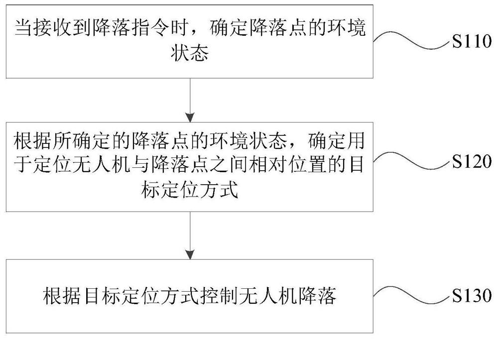
[0050] figure 1 It is a schematic flowchart of a drone landing method provided by Embodiment 1 of the present invention. This embodiment is applicable to the situation where the drone lands on an automatic airport take-off and landing platform at an automatic airport. The method can be executed by a drone landing device, and the device can be realized by software and / or hardware, and integrated into a device with control functions, such as an unmanned aerial vehicle system. The method specifically includes the following steps:

[0051] S110. Determine the environmental state of the landing point when the landing instruction is received.

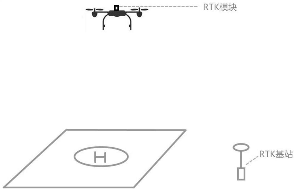
[0052] Wherein, the environmental state may include the light intensity of the area where the landing point is located, or the intensity of the RTK communication signal in the area where the landing point is located.

[0053] Specifically, determining the environmental state of the landing point includes:

[0054] Through the RTK communica...

Embodiment 2

[0077] Figure 4 It is a schematic flow chart of a UAV landing method provided by Embodiment 2 of the present invention. This embodiment has been further optimized on the basis of the above-mentioned embodiments, specifically adding the following steps: when the UAV takes off, the RTK The positioning method determines the coordinates of the take-off point of the drone, and determines the coordinates of the take-off point as the landing point. The advantage of this optimization is that a more accurate landing point position can be obtained, which is conducive to the precise landing of the UAV to the landing point. The explanations of terms that are the same as or corresponding to those in the foregoing embodiments are not repeated here.

[0078] see Figure 4 , the drone landing method provided in this embodiment specifically includes the following steps:

[0079] S210. When the drone takes off, determine the coordinates of the takeoff point of the drone by means of RTK posi...

Embodiment 3

[0089] Figure 5 It is a flow chart of a drone landing method provided by Embodiment 3 of the present invention. This embodiment continues to optimize the scheme on the basis of the above embodiments, specifically for the use of two-dimensional code identification and positioning methods or infrared signal calibration methods. , the process of locating the landing of the UAV is refined, and the explanations of terms that are the same as or corresponding to those in the above-mentioned embodiments will not be repeated here. like Figure 5 Shown, described UAV landing method comprises the steps:

[0090] S310. When receiving the landing instruction, determine the environmental state of the landing point;

[0091] S320. According to the determined environmental state of the landing point, determine that the target positioning method for locating the relative position between the UAV and the landing point is a two-dimensional code identification positioning method or an infrared...


PUM


Abstract

The embodiment of the invention discloses an unmanned aerial vehicle landing method and device, an unmanned aerial vehicle system, an airport, equipment and a medium, and the method comprises the steps: determining the environment state of a landing point when a landing instruction is received, and determining a target positioning mode for positioning the relative position between the unmanned aerial vehicle and the landing point according to the determined environment state of the landing point, and controlling the unmanned aerial vehicle to land according to the target positioning mode. Through the technical scheme of the embodiment of the invention, the unmanned aerial vehicle can accurately land on the automatic airport take-off and landing platform in the automatic airport application, the method is more stable and reliable, and the landing precision of the unmanned aerial vehicle is improved.

Description

technical field [0001] Embodiments of the present invention relate to the technical field of unmanned aerial vehicles, and in particular to a method and device for landing an unmanned aerial vehicle, an unmanned aerial vehicle system, an airport, equipment, and a medium. Background technique [0002] With the express development of UAV technology, UAVs are used in many occasions. For example, in agricultural applications, pesticides are sprayed by UAVs; in shooting applications, UAVs are used for aerial photography; in fire protection applications, Fire fighting by drones, etc. [0003] In the course of realizing the present invention, the inventor finds that there are at least the following problems in the prior art: [0004] The current drones are positioned by GPS (Global Positioning System, Global Positioning System), which is limited by the positioning accuracy of GPS. When the drone automatically lands, there is a large deviation between the actual landing point and t...

Claims


Application Information

Patent Timeline
IPC IPC(8): G05D1/06
CPCG05D1/0676
Inventor 郄新越
Owner BEIJING JINGDONG QIANSHITECHNOLOGY CO LTD
Why Eureka
Try Eureka