Recording apparatus

A technology of recording device and pushing device, applied in the direction of printing device, transportation and packaging, rigid support of bearing parts, etc., which can solve problems such as clearance, easy movement of conveying roller 1001, inability to determine the static position of support 1003 of conveying roller 1001, etc. , to achieve the effect of improving landing accuracy

Inactive Publication Date: 2004-03-17
CANON KK
View PDF2 Cites 5 Cited by
  • Summary
  • Abstract
  • Description
  • Claims
  • Application Information

AI Technical Summary

Problems solved by technology

[0005] Here, even if the pressing force Fp generated by the pinch roller 1004 makes the gap between the conveying roller 1001 and the bearing 1002 and the gap between the bearing 1002 and the support 1003 move downward in the figure, since the cross-sectional shape of the conveying roller 1001 is circular 1. The bearing 1002 is also in a circular shape, and the support 1003 is also in a circular shape. On the inner circumference of the bearing 1002, the conveying roller 1001 is easy to move in the Y, Y' directions. Moving in the direction of Y, Y', when the external force generated by external disturbance is applied, the conveying roller 1001 is easy to move, and the static position of the conveying roller 1001 relative to the support 1003 cannot be determined
[0006] In addition, in the conventional method of providing minute protrusions on the outer peripheral surface of the above-mentioned bearing and inserting the protrusions while cutting the bearing 1002 when mounting the bearing 1002 on the support, although the protrusions are eliminated when the bearing 1002 is inserted, However, when inserting the bearing, it is necessary to have a protrusion that does not deform the inner diameter of the bearing. Therefore, it is necessary to make a protrusion that is easy to cut, that is, weak, and deformed by dropping or vibration during transportation, resulting in a gap.
In addition, resin bearings such as POM generally have different thermal expansions from metal bearings and conveying rollers, so there is a problem that the size changes due to temperature changes, resulting in gaps.

Method used


Image

  • Recording apparatus
  • Recording apparatus
  • Recording apparatus

Examples


no. 1 example

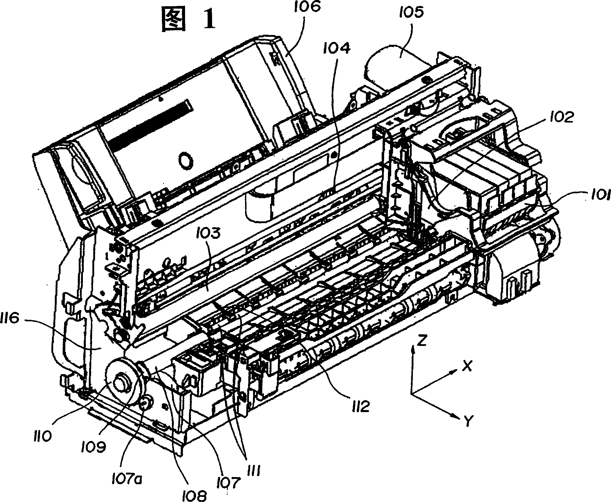
[0021] A description of the first embodiment is made. In this embodiment, a serial inkjet printer equipped with a recording head as a detachable recording device with an ink tank will be described as an example. FIG. 1 is an overall view of a serial inkjet printer. In FIG. 1 , 101 is a recording head having an ink tank, and 102 is a carriage of 101 on which the recording head is mounted. The guide shaft 103 is inserted into the bearing portion of the carriage 102 so as to be slidable in the main scanning direction perpendicular to the conveying direction of the recording medium 301 , and both ends of the shaft are fixed to the holder 116 . The carriage 102 is movable in the main scanning direction (X direction) by transmitting the drive of the driving motor 105 as the carriage driving means through the belt 104 as the carriage driving transmission means coupled to the carriage 102 .

[0022] In Fig. 1, 106 is a supply base storing recording media, 107 is a transport motor as...

no. 2 example

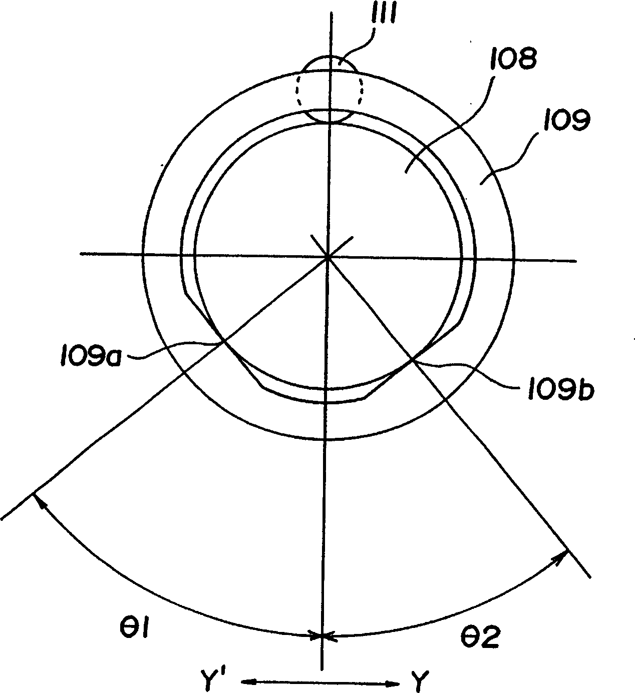
[0082] Figure 7 It is a structural diagram around the conveyance roller and bearings and a conceptual diagram of the acting force, showing the characteristics of the second embodiment of the present invention. Here, the same reference numerals as in the first embodiment have the same meanings. exist Figure 7 In the same manner as in the first embodiment, the conveying roller 108 is pivotally supported by the contact portions 109a and 109b on both surfaces of the bearing 109 . In addition, in this embodiment, the relationship between the bearing 109 and the support 116 is also similar by using the two-surface contact portions 116a, 166b of the support 116 to pivotally support the bearing 109 to eliminate the gap between the bearing 109 and the support 116. The determined position supports the bearing 109 on the support 116 .

[0083] Figure 7 The symbols in mean:

[0084] Ft: force acting on the bearing 109 by the transport roller 108 (Ft is an action vector obtained fr...

no. 3 example

[0095] For the third embodiment of the present invention, same as the second embodiment, Figure 9 A diagram showing the structure around the feed roller and bearings. Here, the same reference numerals as those in the first and second embodiments have the same meanings. In the third embodiment, the contact position angles θc1 and θc2 between the bearing 109 and the support 116 are set to be equal to the contact position angles θ1 and θ2 between the conveyor roller 108 and the bearing 109 obtained in the first embodiment. That is, the contact portions 109 a , 109 b of the bearing and the contact portions 116 a , 116 b of the holder 116 are set to exist on the same straight line passing through the center of the conveying roller 108 . In practice, usually because the mass of the bearing 109 is much smaller than that of the conveying roller 108, the influence of the gravity Fg2 of the bearing 109 can be ignored.

[0096] Therefore, the force received by the bearing 109 from the...


PUM


Abstract

The present invention relates to a recording apparatus which stabilizes the locations of a transfer roller and a bearing and prevents the movement of a recording medium caused by the movement of the transfer roller, to thereby improve the sticking accuracy of the recording device without an increase in cost, comprising a conveyance roller; a driven roller rotating as driven from the conveyance roller; pushing means for pushing the driven roller to the conveyance roller; a bearing for supporting the conveyance roller; driving means for rotating the conveyance roller; and drive transmitting means. The bearing includes two contact portions with the circumference of a spindle for supporting the conveyance roller and the bearing supports the conveyance roller as to locate a perpendicular direction of a line coupling the two contact portions within a varying range of a vector direction of exertion force exerted to the bearing at a time of stop and operation of the conveyance roller.

Description

technical field [0001] The present invention relates to a recording device for forming an image on a recording medium. Background technique [0002] In recent years, the image quality of an output image of a recording device, especially an inkjet recording device, has been greatly improved, and the precision required to realize the image quality has become higher. As a means of improving the image quality of this recording device, there is a proposal to reduce the ink ejection amount to reduce the dot size on the recording medium in order to reduce the graininess of the ink dots ejected on the image. When the dots become smaller, the areas where the dots should overlap are slightly changed when the landing positions of the dots are slightly changed (conversely, the areas that cannot be overlapped overlap), and the density and color tone of the area are deviated. This variation in density or color tone becomes white streaks, black streaks, or color unevenness of the image, d...

Claims


Application Information

Patent Timeline
Patent Type & Authority Applications(China)
IPC IPC(8): B41J13/02B41J13/076B65H5/06F16C13/04F16C17/02F16C35/02
CPCB41J13/076F16C13/04F16C17/02F16C35/02
Inventor 斋藤弘幸
Owner CANON KK
Why Eureka
Try Eureka