Ion implantation method and method for adjusting ion beam scanning rate

A scan rate, ion implantation technology, applied in the field of ion implantation

Active Publication Date: 2013-10-16
ADVANCED ION BEAM TECHNOLOGY INC
View PDF3 Cites 1 Cited by
  • Summary
  • Abstract
  • Description
  • Claims
  • Application Information

AI Technical Summary

Problems solved by technology

However, in this method, in order to provide an ion beam with uniform ion concentration distribution, it takes a considerable amount of time to adjust the uniformity of the ion beam to facilitate subsequent implantation operations. In addition, in addition to the waste of adjustment time, the adjustment technology Difficulty is another problem

Method used


Image

  • Ion implantation method and method for adjusting ion beam scanning rate
  • Ion implantation method and method for adjusting ion beam scanning rate
  • Ion implantation method and method for adjusting ion beam scanning rate

Examples


Embodiment Construction

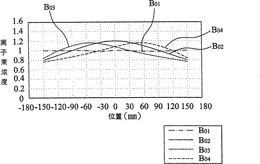
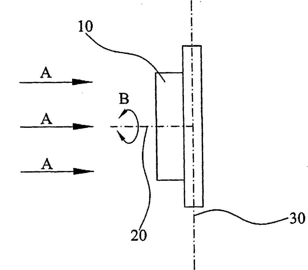
[0050] Continuing the above description, in another embodiment, please refer to figure 1 and figure 2 , figure 2 is a schematic diagram of the target, the axis of rotation and the vertical axis. In this embodiment, the positional relationship between the target, the rotation axis and the vertical axis is as follows figure 2 As shown, the rotation axis (twist) 20 of the target 10 is perpendicular to the target 10 , and the rotation axis 20 is also perpendicular to the vertical axis 30 when the target 10 is not tilted. When the ion beam scans the target 10 in direction A, if the provided ion beam concentration distribution is asymmetric, as figure 1 Concentration curve B03, then, as long as the target 10 is rotated 180 degrees from the original angle, as shown in the double arrow direction B, the ion beam concentration distribution is as follows figure 1 The concentration curve B04 can produce a symmetrical dose distribution.

[0051] Next, in the second embodiment, t...


PUM


Abstract

The invention provides an ion implantation method used for implanting ions into a target. The ion implantation method comprises the step of implanting multiple ions into the target by using a rotating target during constant speed scanning; or implanting the multiple ions into the target by using a variable speed under the premise that the target is not rotated. Ion implantation result with special dose distribution can be obtained without need of providing ion beams with uniform concentration distribution; the process time can be reduced; and the process yield can be increased.

Description

[0001] This application is a divisional application of the invention patent application with the application number "200710162318.X" and the invention title "ion implantation method" submitted by the applicant on September 27, 2007. technical field [0002] The invention relates to an ion implantation method, in particular to an ion implantation method capable of producing special dosage ion distribution. Background technique [0003] In recent years, the manufacturing process of semiconductor devices such as LSI (Large-scale integration, LSI) and memory is quite complicated, and the semiconductor substrate becomes larger in size and extremely expensive. Device size and density is an important issue. Therefore, the practical application of the ion implantation method becomes more important. [0004] Generally speaking, the ion implantation method ionizes molecules to be doped, accelerates the ionized doping, and implants a specific dose of ions into a specific region of ...

Claims


Application Information

Patent Timeline
Patent Type & Authority Patents(China)
IPC IPC(8): H01L21/265H01J37/317
Inventor 林伟政沈政辉
Owner ADVANCED ION BEAM TECHNOLOGY INC
Why Eureka
Try Eureka