Positioning mechanism

A technology of positioning mechanism and limit plate, applied in positioning devices, metal processing equipment, feeding devices, etc., can solve problems such as material waste, achieve the effects of improving economic benefits, saving production costs, and solving material waste

Inactive Publication Date: 2012-01-25
CHERY AUTOMOBILE CO LTD
View PDF5 Cites 9 Cited by
  • Summary
  • Abstract
  • Description
  • Claims
  • Application Information

AI Technical Summary

Problems solved by technology

[0003] The invention provides a positioning mechanism with reliable positioning, simple structure and convenient operation, which can effectively solve the problem of material waste caused by the positioning of large-size material plates in single-action drawing dies

Method used


Image

  • Positioning mechanism
  • Positioning mechanism
  • Positioning mechanism

Examples


Embodiment Construction

[0011] Embodiments of the present invention will now be described with reference to the drawings.

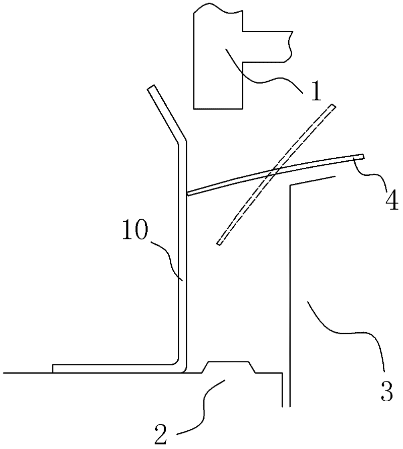
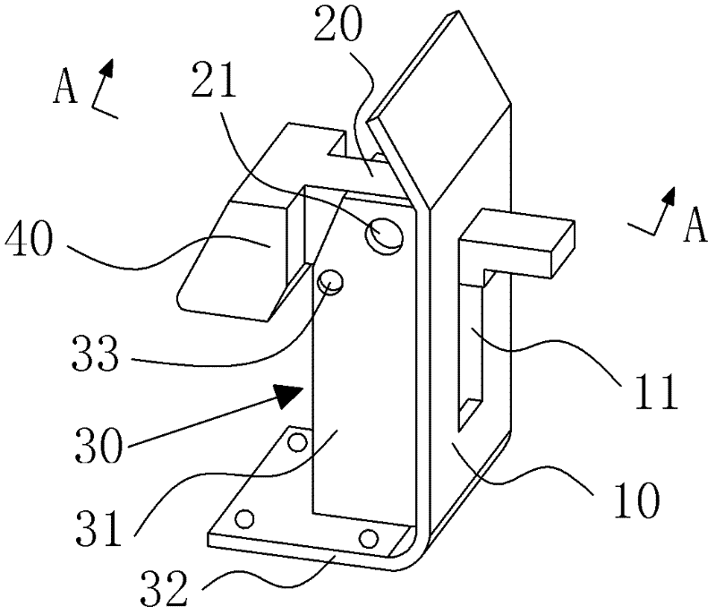
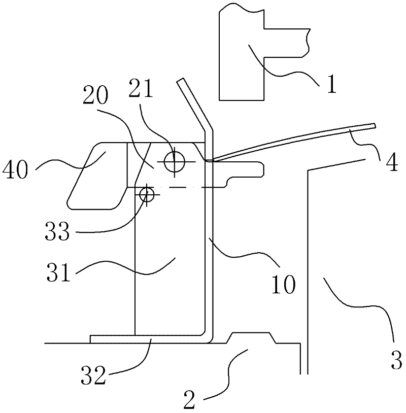
[0012] A positioning mechanism. The positioning mechanism includes a limit plate 10 arranged vertically on the blank holder 2 and a movable part. The movable parts are in two positions respectively. , and the second is to retract to at least the retracted position flush with the plate surface of the limiting plate 10 . By setting up a movable part, when the material plate 4 enters the mould, the movable part is in the protruding position protruding to the front of the limit plate 10, and the material plate is positioned to prevent the suspension end of the material plate 4 from sliding down; 4 When stamped by the mold, the movable part is retracted to at least flush with the plate surface of the limiting plate 10, so that the material plate 4 entering the mold can be well positioned without affecting the material plate 4 Stamping, so that the material plate 4 of appropriate siz...


PUM


Abstract

The invention discloses a positioning mechanism. The positioning mechanism comprises limiting plates which are vertically arranged on a blank holder and a movable member; the movable member has two states, one is a protruding state, namely the movable member protrudes to the front of the limiting plate and the other is a retraction state, namely the movable member retracts to the position at least flush with the plate surface of the limiting plate. The invention is characterized by arranging the movable member; the movable member is in the protruding state, namely protrudes to the front of the limiting plate to fix the position of a material plate and prevent the a suspended end of the material plate from sliding off when the material plate enters into a mould; when the material plate is punched by the mould, the movable member is in the retraction state, namely retracts to the position which is flush with the plate surface of the limiting plate at least, so that the material plate which enters into the mould can be better positioned and the punching of the material plate is not affected. The positioning mechanism is reliable in positioning, simple in structure and convenient in operation, and the problem of material waste and the like because the positioning is realized through the large-sized material plate in a single action drawing mould can be solved effectively.

Description

technical field [0001] The invention belongs to the field of automobile stamping die equipment, and in particular relates to a positioning mechanism. Background technique [0002] With the continuous advancement of science and technology, the performance of automobiles has been continuously improved. While pursuing the high performance of automobiles, people also put forward higher requirements for the appearance of automobiles, and are increasingly pursuing beautiful bodywork. The shape of the car body is related to the stamping parts that make up the car body. The streamlined body of the car is composed of the complex shape and concave-convex profile of the stamping parts. The stamping parts of the car body are completed in the single-action drawing die. By adding the material plate 4 into the mold, the upper touch 1 moves downward to squeeze the material plate 4 downward, and the upper touch 1 and the blank holder 2 are pressed together. , driving the material plate 4 to...

Claims


Application Information

Patent Timeline
Patent Type & Authority Applications(China)
IPC IPC(8): B21D37/10B21D43/00
Inventor 彭文会仇保虎王荣才方立宏黄和平
Owner CHERY AUTOMOBILE CO LTD
Why Eureka
Try Eureka