Broken yarn pneumatic processing device of ring spinner

A ring spinning machine and processing device technology, applied in textiles and papermaking, etc., can solve problems such as inconvenient operation, inconvenient operation, and defective detection methods

Inactive Publication Date: 2012-01-25
绍兴华裕纺机有限公司
View PDF7 Cites 14 Cited by
  • Summary
  • Abstract
  • Description
  • Claims
  • Application Information

AI Technical Summary

Problems solved by technology

This treatment method and device have the following problems: 1. Since the broken yarn strands are still continuously provided, they are absorbed by the suction pipe, thus causing a large amount of waste of strands; Expensive
But in production practice, it is found that there are still the following defects: 1. The detection method is defective and inconvenient to operate. When doffing each time, the detection rod may slip off from the yarn, resulting in the failure of judging whether the yarn is open or broken. According to the loss, it is necessary to put the detection rod back on the yarn, and the operation is even more inconvenient; 2. The power to open the air valve switch is insufficient, and the yarn breakage detection rod falls under gravity when the yarn is broken and provides the driving force for the air valve switch Smaller, the range of application of the yarn is limited

Method used


Image

  • Broken yarn pneumatic processing device of ring spinner
  • Broken yarn pneumatic processing device of ring spinner
  • Broken yarn pneumatic processing device of ring spinner

Examples


Embodiment 1

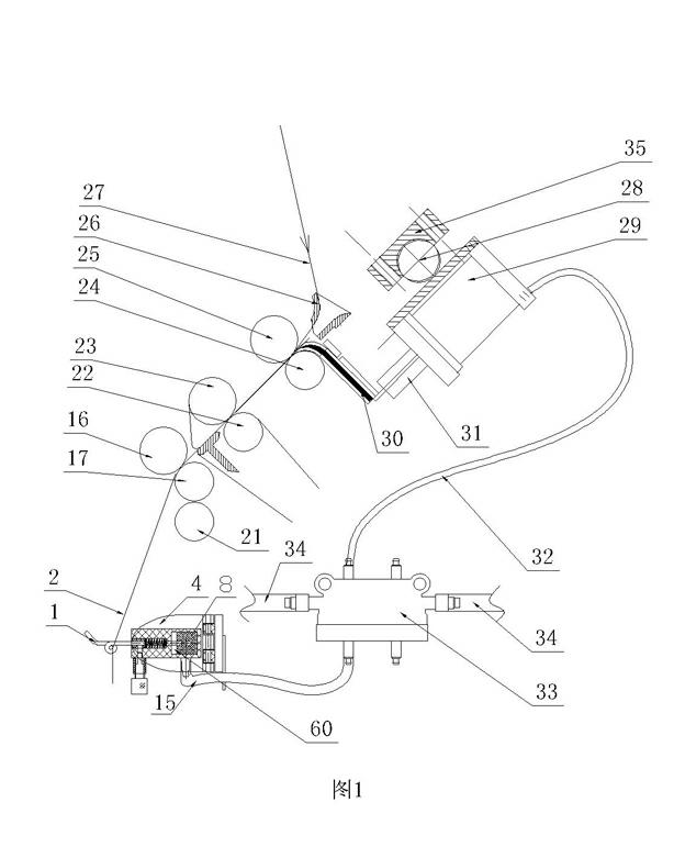
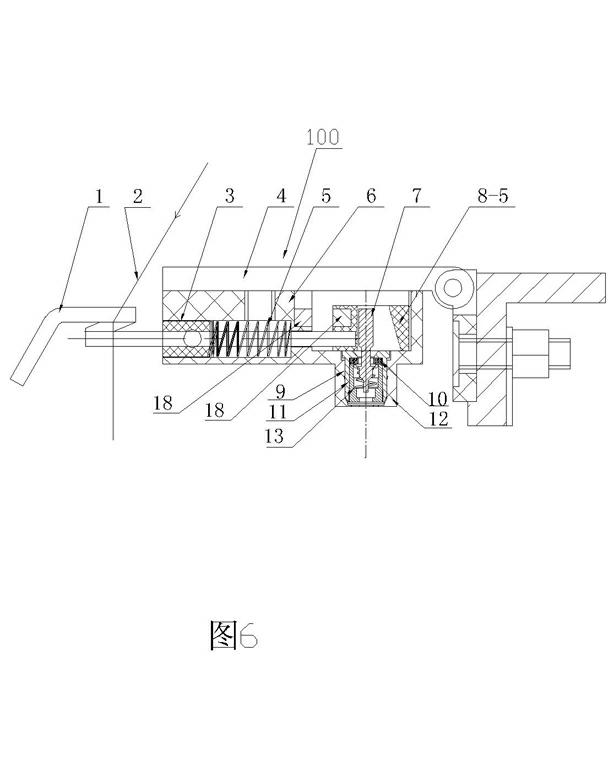
[0034] Such as figure 1 As shown, it is a schematic diagram of the operation of the pneumatic processing device for broken yarn on the ring spinning machine of the present invention when the yarn is guided. Such as figure 2 , diagram 2-1 Shown is a schematic structural view and a top view of the gas valve switch in the embodiment of the present invention.

[0035] In the ring spinning machine, the roving 27 enters the holding area formed by the rear roller 24 and the rear top roller 25 through the yarn guide 26, and guides the holding area between the middle roller 22 and the middle top roller 23, and then guides the front The gripping area between the roller 17 and the front top roller 16 forms the yarn 2 after multi-pass drafting and twisting, and the yarn guide hook 1 is installed under the front roller 17 and the front top roller 16. The above structure is a common technology in the field of ring spinning machines, and will not be repeated here.

[0036] The broken y...

Embodiment 2

[0048] Such as image 3 , Figure 3-1 As shown, the structure and working principle are the same as in Embodiment 1, the difference is that the inside of the limit block is wedge-shaped, the slope faces to the left, a pair of magnetic devices are formed, and the trachea faces downward.

Embodiment 3

[0050] Such as Figure 4 , Pic 4-1 As shown, the structure and working principle are the same as in Embodiment 1, the difference is that the inside of the limit block is ring-shaped, two sets of paired magnetic devices, and the trachea faces to the right.


PUM


Abstract

The invention discloses a broken yarn pneumatic processing device of a ring spinner, which comprises a yarn guide hook, an actuator cylinder, an air dividing valve and an air valve switch, wherein the air valve switch comprises a yarn guide hook turning plate, a shell internally provided with a cavity, a pressure spring, a pressure regulator block, a limit block and a valve rod; the lower end of the valve rod, an outer bushing, an inner lining tube and a sealing gasket form a sealing cavity when the valve rod is vertical to the straight handle end of the yarn guide hook; and the valve rod canbe pushed for opening or closing the sealing cavity through the movement of the limit block. In the scheme, the broken yarn processing device is designed by using the principle that the pressure state of the yarn guide hook is different between two states of guiding yarns and breaking the yarns, and the elasticity of the spring and the magnetic force of a magnetic device are used as a dual-pushing force, thus the action adaptability of the air valve switch under different conditions of high count yarns, medium count yarns and low count yarns is enlarged, and the purpose of expanding the application range of the broken yarn processing device is achieved.

Description

technical field [0001] The invention relates to a ring spinning machine, in particular to a broken yarn pneumatic processing device of the ring spinning machine. Background technique [0002] Yarn breakage is a common problem in spinning. In the prior art, when the ring spinning machine breaks the yarn, the method and device that the suction pipe continuously absorbs the drawn broken yarn strands are used to deal with the broken yarn accident. The processing method and device have the following problems: 1. Since the broken yarn strands are still continuously provided, they are absorbed by the suction pipe, thus causing a large amount of waste of strands; Expensive. [0003] In response to the above problems, the applicant once disclosed a yarn breakage processing device for ring spinning machines (Chinese patent 201020618311.1), which uses a rotatable yarn breakage detection rod, one end of which is overlapped on the yarn, and the movement track of the other end An air v...

Claims


Application Information

Patent Timeline
Patent Type & Authority Applications(China)
IPC IPC(8): D01H13/16D01H11/00
Inventor 刘光容朱爱萍
Owner 绍兴华裕纺机有限公司
Why Eureka
Try Eureka