Stamping device and stamping pipe

A technology of mold printing and pulling device, which is applied in the field of mold printing tubes, and can solve the problems that heat shrinkable tubes cannot be realized, etc.

Active Publication Date: 2012-02-01
SHENZHEN WOER HEAT SHRINKABLE MATERIAL
View PDF6 Cites 0 Cited by
  • Summary
  • Abstract
  • Description
  • Claims
  • Application Information

AI Technical Summary

Problems solved by technology

[0002] Existing marking on the surface of the heat shrinkable tube is generally done by printing or engraving patterns on the mold. At present, the segmented heat shrinkable tube can be marked through the mold, and the method of marking the continuous heat shrinkable tube with the mold cannot be realized.

Method used


Image

  • Stamping device and stamping pipe
  • Stamping device and stamping pipe
  • Stamping device and stamping pipe

Examples


Embodiment Construction

[0039] In order to describe the technical content, structural features, achieved goals and effects of the present invention in detail, the following will be described in detail in conjunction with the embodiments and accompanying drawings.

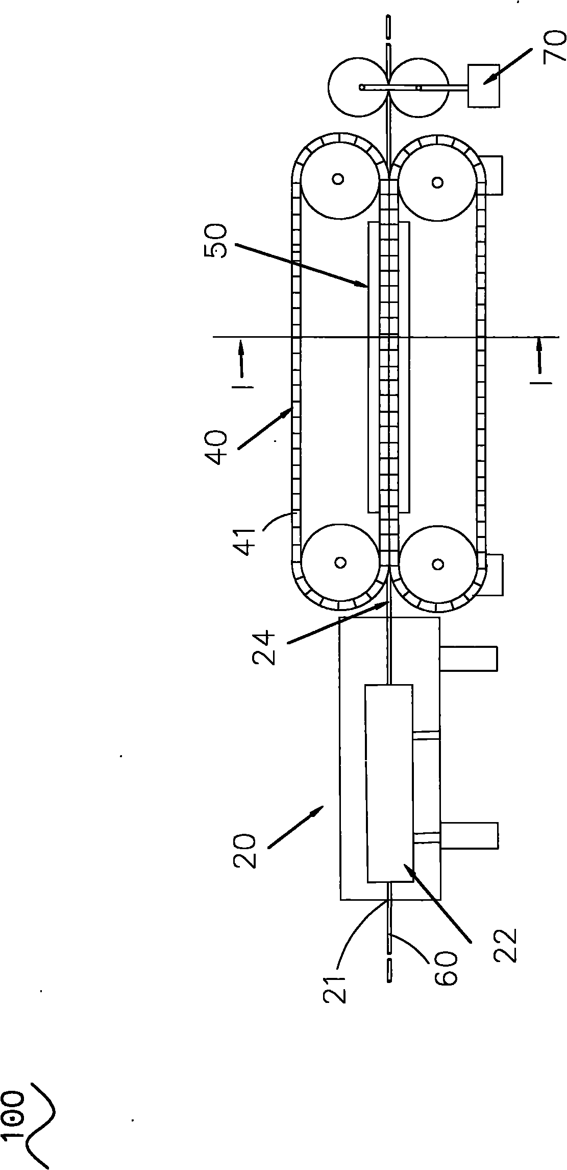
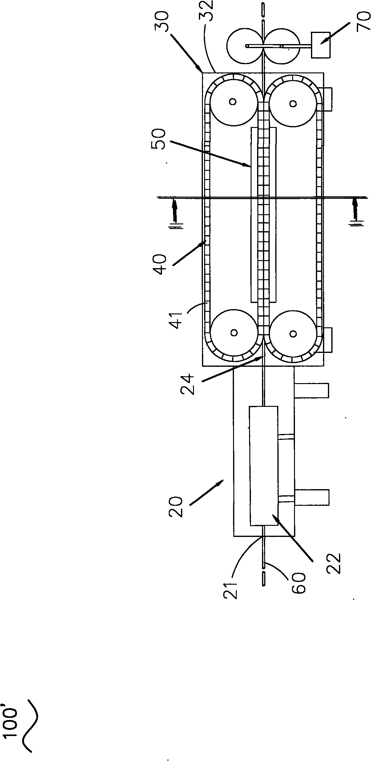
[0040] see figure 1 and figure 2 , which discloses the first embodiment of the stamping device 100 of the present invention, the stamping device 100 of the present invention includes a sealed box 20, an air pressure regulating device (not shown in the figure), two crawlers 40, several shoes 41 and traction device 70.

[0041] The sealing box 20 is a hollow sealing box, which is roughly in the shape of a cylinder, and has a perforation 21 passing through the sealing box 20. The perforation 21 has an annular hole wall, and the hole wall is in sealing connection with the outer wall of the sealing box 20. A hollow airtight box is formed. The perforation 21 is used as a passage for the heat-shrinkable tube 60 to penetrate. Of course, the se...


PUM


Abstract

The invention discloses a stamping device. The stamping device comprises a sealing box, an air pressure regulation device, two tracks, a plurality of track blocks and a drawing device; the sealing box is adjacent to two tracks; the sealing box is provided with a through hole; the through hole is provided with a hole wall which is in sealed connection with an outer wall of the sealing box to form a hollow sealing box body; a plurality of track blocks are arranged on the tracks; the track blocks are provided with model parts which are provided with corresponding patterns; and the two tracks are adjacent in the vertical direction and can move in an opposite direction. In the stamping device, a thermal shrinkage pipe passes through the through hole of the sealing box to be prevented from being expanded before stamping, and is drawn by the drawing device to advance, and expanded by the air pressure regulation device, and two tracks are adjacent in the vertical direction and move in the opposite direction, so that the stamping is realized and large-scale continuous expansion and stamping of the thermal shrinkage pipe are realized. Moreover, the invention also discloses a stamping pipe on which a stamping mark disappears when the stamping pipe is heated; and the stamping is finished when the stamping pipe is expanded, so the stamping mark can disappear when the stamping pipe is heated and shrunk.

Description

technical field [0001] The invention relates to a stamping device and a stamping tube, in particular to a stamping device for tubes such as heat-shrinkable tubes and a stamping tube whose stamping marks will disappear when heated and shrunk. Background technique [0002] Existing marking on the surface of heat shrinkable tubes is generally done by printing or engraving patterns on molds. At present, segmental heat shrinkable tubes can be marked through molds, but the method of marking continuous heat shrinkable tubes with molds cannot be realized. Contents of the invention [0003] The main object of the present invention is to provide a device capable of expanding and embossing a mold for continuous heat-shrinkable tubing. [0004] Another object of the present invention is to provide an embossed tube in which an embossed mark disappears when heated. [0005] In order to achieve the above-mentioned main purpose, the present invention provides a stamping device, including...

Claims


Application Information

Patent Timeline
Patent Type & Authority Applications(China)
IPC IPC(8): B41K3/00
Inventor 康树峰周和平
Owner SHENZHEN WOER HEAT SHRINKABLE MATERIAL
Why Eureka
Try Eureka