

Endoscope
A technology for endoscopes and lenses, applied in the field of endoscopes, can solve problems such as difficulty in securing space for side-view lighting units, and failure to disclose the structure of side-view lighting units
- Summary
- Abstract
- Description
- Claims
- Application Information
AI Technical Summary
Problems solved by technology
Method used
Image

Examples
no. 1 Embodiment approach
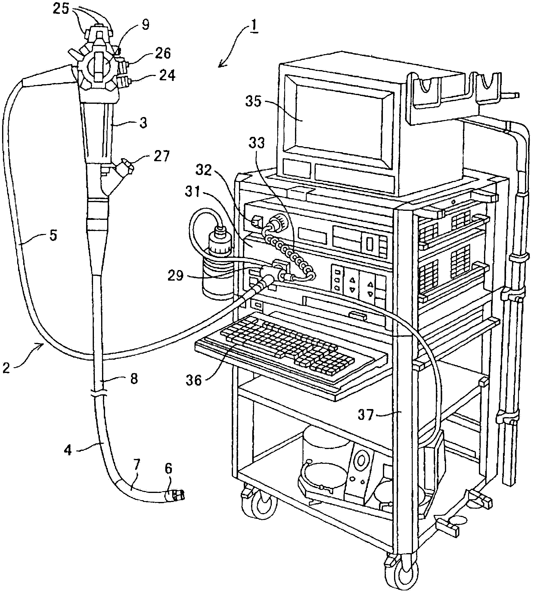
[0034] Such as figure 1 As shown, the endoscope apparatus 1 according to the first embodiment of the present invention has an endoscope 2 for performing endoscopic inspection. This endoscope 2 is constituted by the following parts: the operation part 3 which is grasped and operated by the operator; the elongated insertion part 4 formed at the front end of the operation part 3 and inserted into the body cavity; and the base end. A universal cord 5 extending from the side of the operating part 3.
[0035] In addition, the insertion part 4 is composed of the following parts: a hard front end part 6 provided at the front end, a bendable bending part 7 provided at the rear end of the front end part 6, and a long and flexible part provided at the rear end of the bending part 7. The flexible tube portion 8 and the bending portion 7 can be bent by the bending operation lever 9 provided on the operating portion 3 .
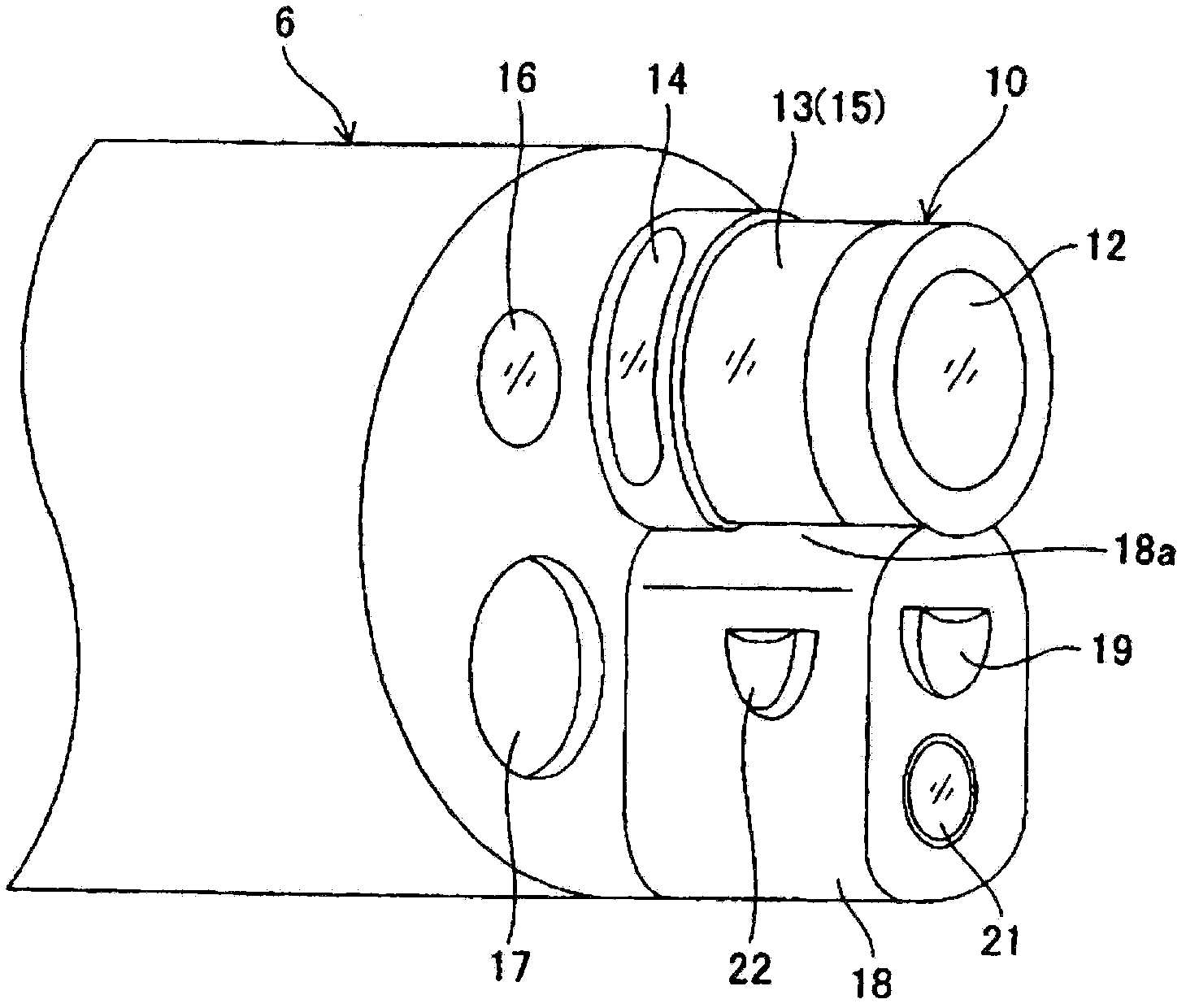
[0036] In addition, if figure 2 As shown, on the front end portio...
no. 2 Embodiment approach
[0105] Next, a second embodiment of the present invention will be described. Figure 10 The structure of the side view illuminating part in 2nd Embodiment of this invention is shown with a cross-sectional view.
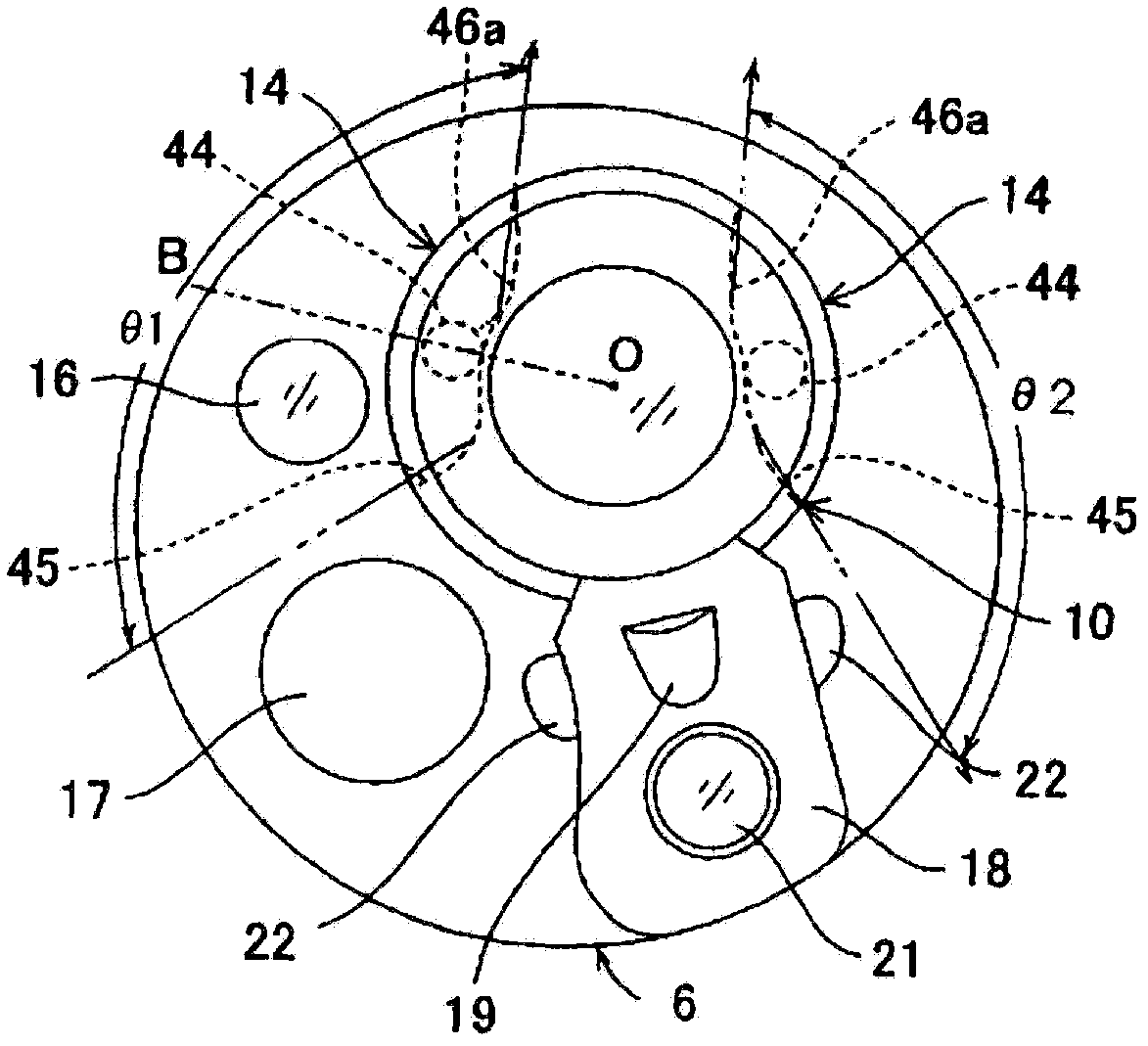
[0106] The side viewing lighting part in the present embodiment adopts the side viewing lighting window 14a as follows: for example, in one side viewing lighting window 14 of the side viewing lighting part of the first embodiment, the reflective member 46 (light guide groove) 45) of the inner surface of the reflective portion 46a at both ends in the circumferential direction are a planar reflective surface 61 and a stepped reflective surface 62, respectively.
[0107] In addition, in the present embodiment, the side viewing lighting window 14b is adopted in which the circumferential direction of the reflective portion 46a provided on the inner surface of the reflecting member 46 in the other side viewing lighting window 14 in the first embodiment is adopted. Both end...
no. 3 Embodiment approach
[0118] Figure 11 The structure of the side view illuminating part in 3rd Embodiment of this invention is shown with a cross-sectional view. This embodiment and for example Figure 8 Similar to the second modified example shown, three side-view lighting windows 14c, 14d, and 14e are provided. However, shown with Figure 8 The configuration example of the case is different.
[0119] And, the side view lighting windows 14c, 14d, 14e are in the Figure 8 In the shown structure of the side-view lighting window 14, a light-scattering material 71 and a transparent filler 72 are filled inside the light-guiding groove 45 to form a light-guiding member, and the light-scattering material 71 serves as a light-scattering member that scatters light. , composed of glass particles, etc.
[0120] In addition, the filler 72 has the function of maintaining the light scattering material 71 in an appropriate distribution or density, so that the light scattering material 71 as a whole has a f...
PUM
 Abstract
Description
Claims
Application Information