Reinforced masonry panel structures

A technology of masonry structure and steel bars, applied in building components, building structures, walls, etc., can solve acoustic problems and other problems

Inactive Publication Date: 2009-10-14
WEMBLEY INNOVATION
View PDF1 Cites 21 Cited by
  • Summary
  • Abstract
  • Description
  • Claims
  • Application Information

AI Technical Summary

Problems solved by technology

[0004] 2. A frame connector with a center spacing of 225mm must be set between the masonry on both sides and the wind column
[0007] 5. There may also be acoustic problems
[0008] 7. The wind post usually needs four bolts to fix, 2 at the bottom and 2 at the soffit
[0009] 8. The wind column must be erected before the wall is built, so in order to implement safe operations, especially high-altitude operations, isolation channels (such as scaffolding) are required

Method used


Image

  • Reinforced masonry panel structures
  • Reinforced masonry panel structures
  • Reinforced masonry panel structures

Examples


Embodiment Construction

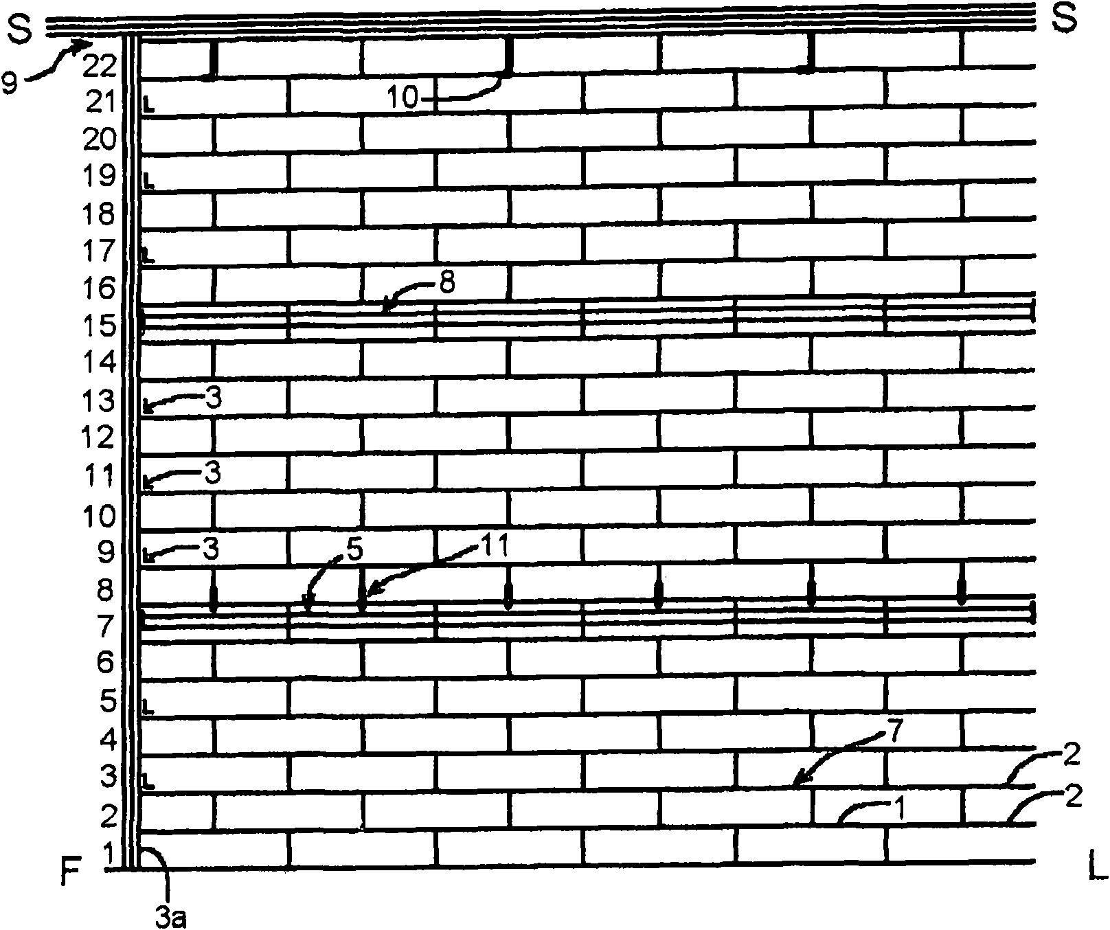
[0053] figure 1 The section of infill wall shown schematically in consists of 22 layers of blocks (labeled 1-22 from ground floor FL to soffit SS) laid with standard 10mm mortar joints and incorporating two vertically spaced joints beam. Wall material specifications are as follows:

[0054] 1. The first floor D.P.C.

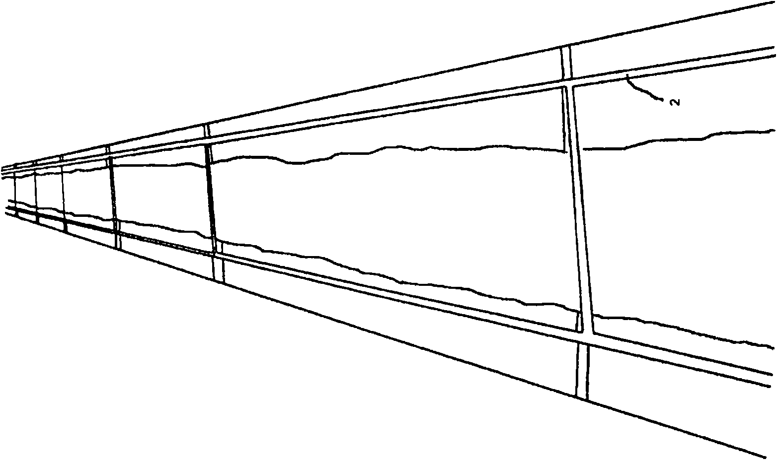
[0055] 2. Each layer of flat seam reinforcement (center distance 225mm), BRC3.5mm galvanized.

[0056] 3. 175mm at the center distance of 450mm to the vertical end steel part 3a Frame connectors.

[0057] 4. 12mm thick x 140mm wide at the vertical junction of steel parts and blocks Expansion seam strips.

[0058] 5. The seventh layer combined beam:

[0059] External dimensions of hollow blocks (in mm, used to match other blocks in the wall): 140W×215D×440L

[0060] Internal dimensions of the hollow part (in mm, per block): 80W×167D×440L. This provides sufficient strength for the resulting bonded beam, sufficient concrete cover for corrosion protectio...


PUM

PropertyMeasurementUnit
lengthaaaaaaaaaa

Abstract

A method of constructing a masonry infill in a load bearing structure comprises the steps of: laying one or more courses of masonry (7) in the infill space; partitioning off a casting space having as its base the then uppermost course of masonry (22); the casting space extending from one side of the infill space to the other; positioning reinforcing material (14) in the casting space; securing an end of the reinforcing material to the load bearing structure; filling the casting space with concrete (20), and laying one or more further courses of masonry on top of the filled casting space. The reinforced concrete forms a bond beam which strengthens the masonry. The reinforcing material may be rebar, secured to a load-bearing frame of the building by a cleat (16) having pockets (12) for reception of the rebar ends. Optionally the reinforcement may be tensioned, to pre-stress the bond beam. The bond beam may also be used to strengthen bonded, load-bearing masonry panels in bending, without being secured to an adjacent load-bearing structure.

Description

Background technique [0001] Current techniques for constructing large buildings typically involve load-bearing frames of steel or reinforced concrete, and the use of additional cladding and / or masonry fill. In the case of masonry walls of such structures and elsewhere, it is necessary to provide additional reinforcement where the area of ​​the wall increases beyond a certain limit. Reinforcement is used to support the weight of a wall; to resist environmental loads such as wind, air pressure differentials and earthquakes, and to withstand other dynamically acting loads such as crowd pressure, vehicle impacts or explosions. The required strength of a prescribed structure is constrained not only by the laws of physics, but also by local building codes. [0002] Walls have traditionally been supported by transverse walls, piers and wall thickenings wherever additional strength is required. More recently, standard windposts have been developed which are found in most such walls ...

Claims


Application Information

Patent Timeline
Patent Type & Authority Applications(China)
IPC IPC(8): E04B2/24E04B1/41E04G21/12
CPCE04B1/165E04B1/4107E04B2/24E04B2002/0254E04C2/041F16B9/052F16B9/056E04B2/20E04B2/64E04B2/68E04H9/02E04H9/021
Inventor L·克利尔
Owner WEMBLEY INNOVATION
Why Eureka
Try Eureka